Vacuum-evaporation source, and organic EL element manufacturing apparatus

A technology for manufacturing a device and an evaporation source, which is applied in the field of evaporation sources, can solve the problems of difficulty in correctly controlling the temperature of evaporation materials, infiltration of organic materials, and poor temperature responsiveness, and achieves shortened startup time, effective utilization, and thermal responsiveness. high effect

Active Publication Date: 2010-09-29
ULVAC INC
View PDF1 Cites 9 Cited by
  • Summary
  • Abstract
  • Description
  • Claims
  • Application Information

AI Technical Summary

Problems solved by technology

[0003] Therefore, the temperature responsiveness of the crucible is poor, and it is difficult to accurately control the temperature of the vapor deposition material in the crucible.
In addition, when filling the crucible with an organic material as a vapor deposition material, depending on the type of organic material, the organic material may infiltrate into the crucible.

Method used


Image

  • Vacuum-evaporation source, and organic EL element manufacturing apparatus
  • Vacuum-evaporation source, and organic EL element manufacturing apparatus
  • Vacuum-evaporation source, and organic EL element manufacturing apparatus

Examples


Embodiment Construction

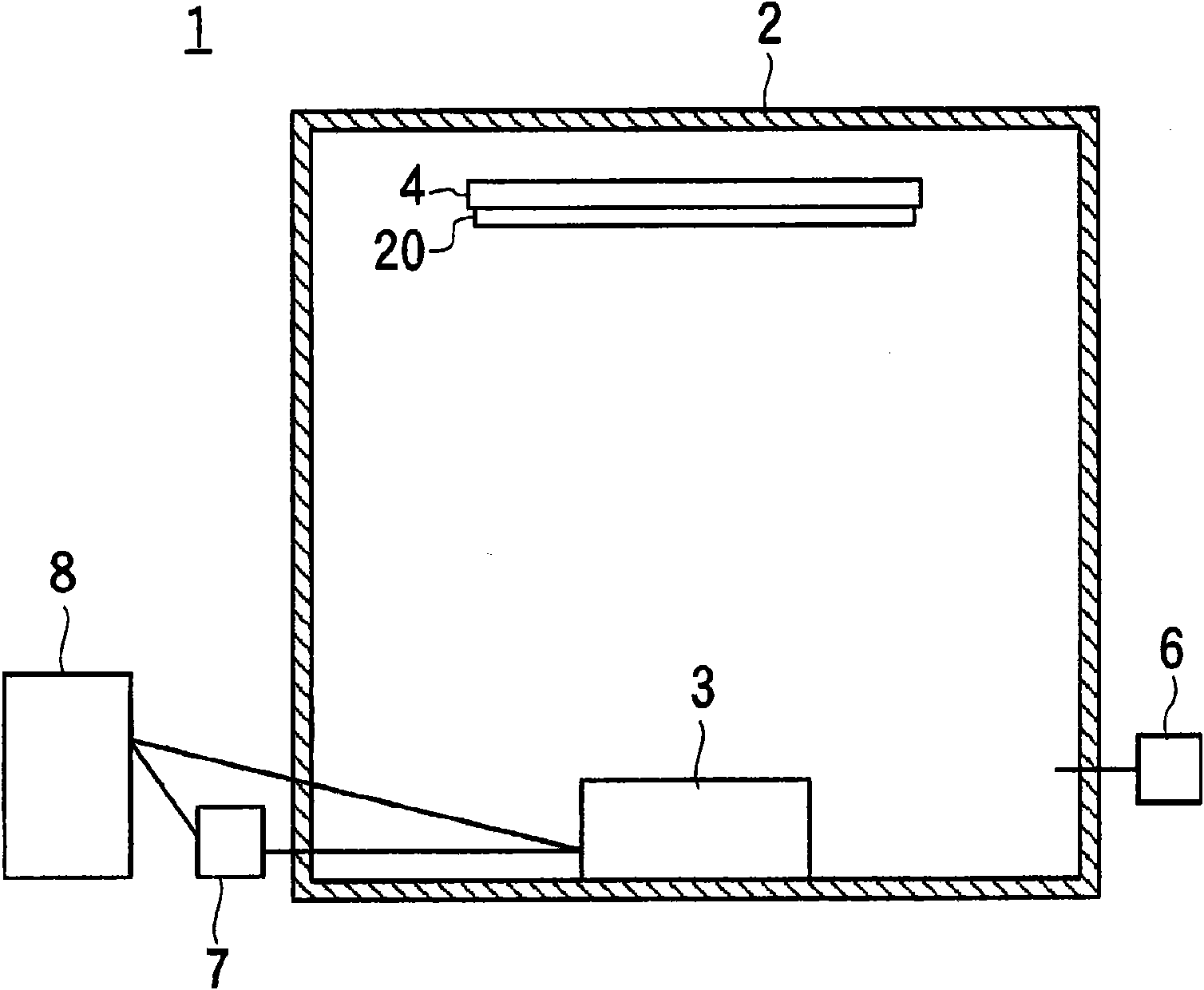
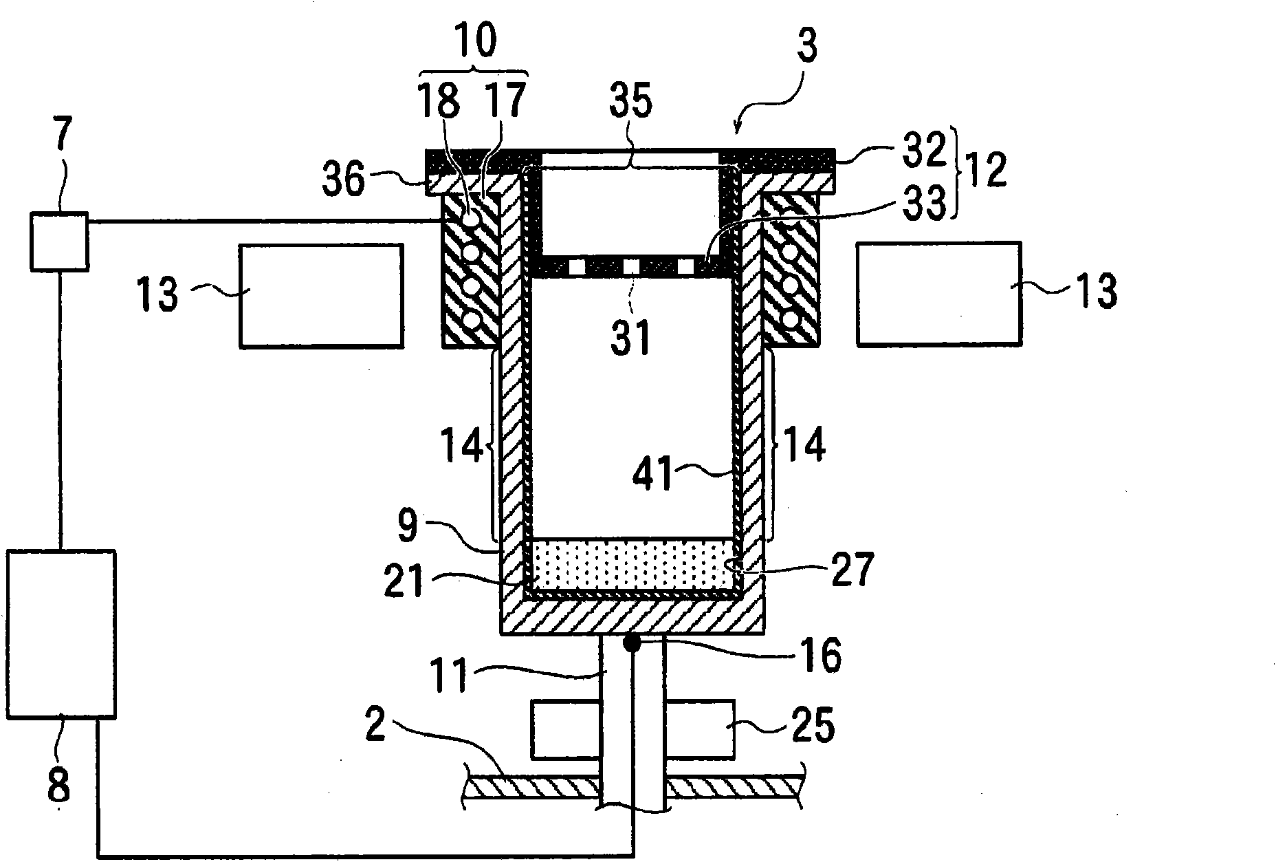
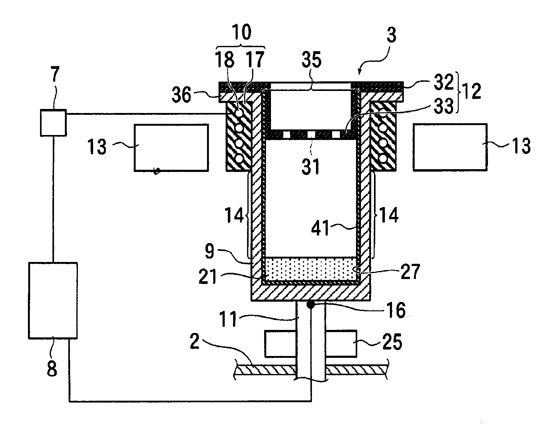
[0030] figure 1 The reference numeral 1 in the figure shows the manufacturing apparatus (vacuum evaporation apparatus) of the organic EL element which is an example of this invention. The vacuum evaporation device 1 has a vacuum tank 2 . A vapor deposition source 3 is arranged below the inside of the vacuum chamber 2 , and a substrate holder 4 is arranged above it. Evaporation source 3 such as figure 2 Shown are: evaporation vessel 9 , heating means 10 , and water cooling shroud 13 .

[0031] The heating device 10 has a ring shape and has a ring-shaped heat homogenizer 17 made of a material with high thermal conductivity. The heat spreader 17 is arranged in the vacuum chamber 2 so that its central axis is substantially vertical.

[0032] The evaporator 9 is vertically inserted into the ring of the heat homogenizer 17 with the opening 35 facing upward (the top side of the vacuum chamber 2 ).

[0033] Inside the heat spreader 17, a heating wire 18 wound concentrically with...


PUM

PropertyMeasurementUnit
diameteraaaaaaaaaa
heightaaaaaaaaaa

Abstract

This aims to improve the heat controllability of an evaporation container (9) of a vacuum-evaporation source. This vacuum-evaporation source (3) comprises the evaporation container (9) having an organic material (21) arranged therein, and a heater wire (18) wound on the outer circumference of the evaporation source (3). The organic material (21) is arranged such that its portion to contact the sidewall of the evaporation container (9) is below the lower end of the heater wire (18), and a substrate (20) is attached to a substrate holder (4). When a power source (7) is started so that the heater wire (18) generates heat to heat the evaporation container (9), the vapor of the organic material (21) is released from an upward through hole (31) to the inside of a vacuum bath (2), so that it sticks to the substrate (20) thereby to form a thin film. The heater wire (18) is arranged up to the upper end of the evaporation container (9), so that it can heat the opening to an evaporation temperature or higher. The evaporation container (9) is made of a metal material selected from at least one kind of copper, an alloy of copper and beryllium, Ti and Ta, and is formed to have a side wall and abottom wall of a thickness of 0.3 mm to 0.7 mm. Thus, the vacuum-evaporation source (3) has a small heat capacity and excellent controllability.

Description

technical field [0001] The present invention relates to a vapor deposition source and a device using the vapor deposition source. Background technique [0002] Conventionally, a graphite vessel has been used as an evaporation vessel (crucible) of a vapor deposition apparatus. Since the graphite crucible requires a certain wall thickness, the crucible becomes heavy and has a large heat capacity. [0003] Therefore, the temperature responsiveness of the crucible is poor, and it is difficult to accurately control the temperature of the vapor deposition material in the crucible. In addition, when filling the crucible with an organic material as a vapor deposition material, depending on the type of the organic material, the organic material may infiltrate into the crucible. [0004] Patent Document 1: Japanese Patent Application Laid-Open No. 2005-97730 Contents of the invention [0005] The problem to be solved by the invention [0006] The present invention was made in or...

Claims


Application Information

Patent Timeline
Patent Type & Authority Applications(China)
IPC IPC(8): C23C14/24
CPCC23C14/12C23C14/243C23C14/24H01L21/02631H10K50/00
Inventor 永田纯一
Owner ULVAC INC
Why Eureka
Try Eureka