Cylinder and piston co-rotating type engine

An engine and co-rotation technology, applied in variable displacement engines, internal combustion piston engines, reciprocating piston engines, etc., can solve the problems of high processing cost, long and narrow, insufficient fuel combustion, etc., achieve high energy conversion efficiency and reduce use Cost, the effect of sufficient fuel combustion

Inactive Publication Date: 2013-12-11
谢坤
View PDF5 Cites 0 Cited by
  • Summary
  • Abstract
  • Description
  • Claims
  • Application Information

AI Technical Summary

Problems solved by technology

1. The reciprocating motion makes the limit speed of the engine lower
2. The reciprocating engine is equipped with a ventilation valve mechanism, which not only increases the volume of the whole machine, but also increases the weight of the whole machine
3. The crankshaft and connecting rod are used for power transmission. When the piston is close to the top dead center and the bottom dead center, the effective force arm of the gas expansion force on the crankshaft is very small, the expansion force in the cylinder cannot be fully exerted, and the energy conversion rate is low.
4. The power-to-weight ratio of the whole machine is too small, so it is not suitable for application in the aviation direction
1. The eccentric rotation of the triangular rotor will produce a lot of vibration
2. The shape of the cylinder formed between the triangular rotor and the cylinder wall is narrow and long, which makes the fuel combustion insufficient
3. When the engine is working, the pressure of the expanded gas in the cylinder is decomposed, and the effective torque is very small, so that the energy conversion efficiency of the engine is lower than that of the reciprocating engine, and the fuel consumption is high. It is only used in high-speed racing cars or airplanes, and is not suitable for civilian use.
4. The shape of the triangular rotor and the shape of the cylinder are very precise, and the processing cost is high

Method used


Image

  • Cylinder and piston co-rotating type engine
  • Cylinder and piston co-rotating type engine
  • Cylinder and piston co-rotating type engine

Examples


Embodiment Construction

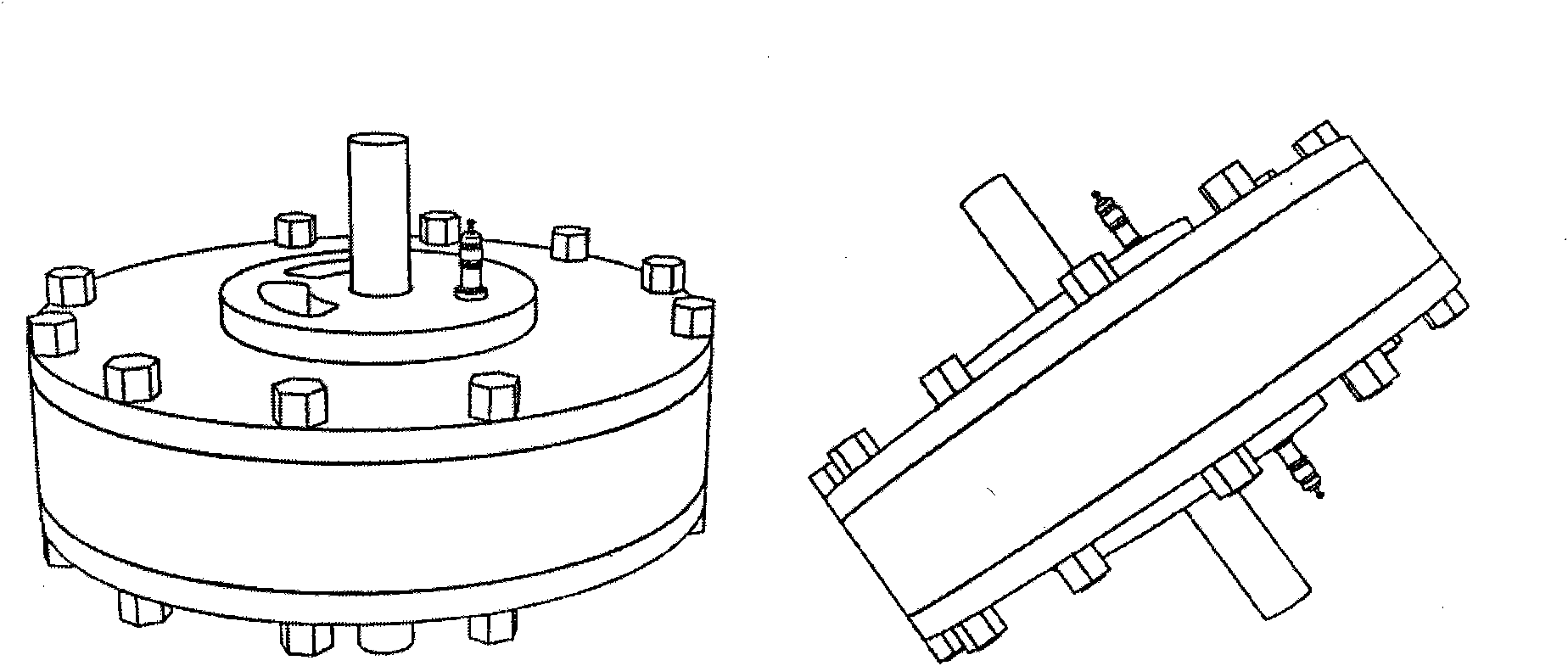
[0027] Such as figure 1 Shown is the schematic diagram of the appearance of the engine. From the figure, it can be understood that the shape of the engine of the present invention is a disk, and the output shaft (1) protrudes from the center point position of the upper and lower end faces of the disk, and is used to connect the load equipment. The stator of the engine is composed of upper, middle and lower shell components, and is fixed by a circle of multiple shell bolts. At the positions where the upper and lower ends of the disk are adjacent to the output shaft, two upper and lower spark plugs (4) are installed on one side of the output shaft, and two pairs of upper and lower arc-shaped air inlets and exhaust are arranged on the other side.

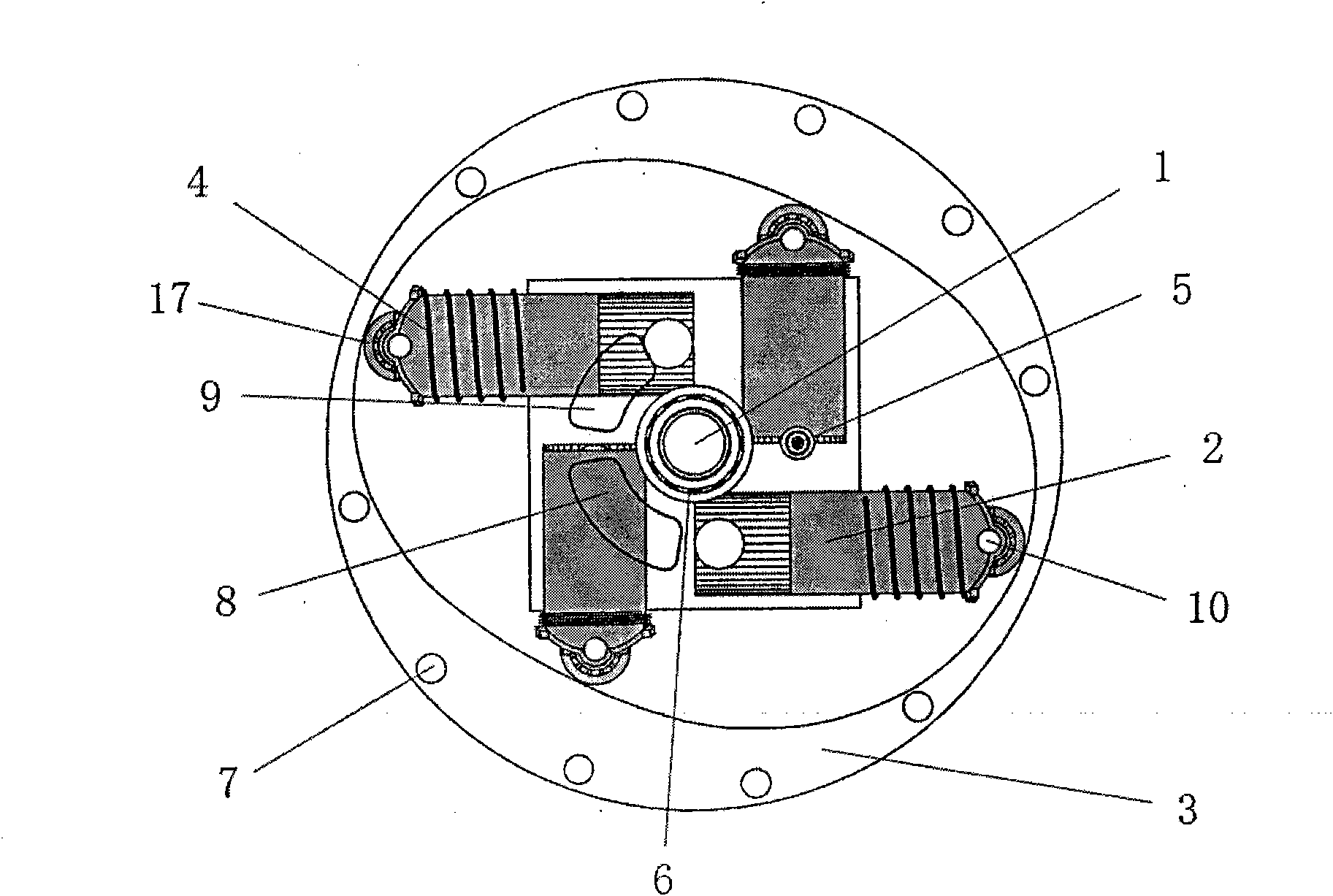
[0028] Such as figure 2 Shown is the cross-sectional schematic diagram of the present invention, has marked several important members of the present invention among the figure, observes schematic diagram and can understand, and in en...


PUM


Abstract

The invention relates to a cylinder and piston co-rotating type engine which comprises a rotor and a stator. A cylinder rotor is formed by a column type component and a plurality of cylinders shifting a certain distance on the periphery of the column type component, and an output shaft is inserted in the center of the column type component. A stator assembly is formed by arranging a stator housing, an upper housing cover and a lower housing cover in parallel, wherein the housing covers are provided with intake and exhaust vents, and the stator housing has an oval cavity. When the rotor rotates in a non-eccentric mode in the stator, a rotor bearing at the tail end of a piston in the cylinders can slide on the oval inner side wall of the stator so that the capacity of the cylinders can be changed periodically, a four-stroke principle is realized, and thus the engine has a high ratio of power to weight.

Description

a technical field [0001] The invention relates to a cylinder-plug co-rotating engine, in particular to an engine in which a cylinder and a piston continuously rotate in an elliptical space to realize the four-stroke principle. Two background technology [0002] Among the existing engines, the ones with more mature technology are mainly reciprocating piston engines and Wankel triangular rotor engines for vehicles. Wherein the reciprocating engine has several problems that cannot be avoided. 1. The reciprocating motion makes the limit speed of the engine lower. 2. The reciprocating engine is provided with an air exchange valve mechanism, which not only increases the volume of the whole machine, but also increases the weight of the whole machine. 3. The crankshaft and connecting rod are used for power transmission. When the piston is close to the top dead center and the bottom dead center, the effective force arm of the gas expansion force on the crankshaft is very small, the...

Claims


Application Information

Patent Timeline
Patent Type & Authority Patents(China)
IPC IPC(8): F01B13/04F02B57/00
Inventor 尚世群
Owner 谢坤
Why Eureka
Try Eureka