
Two-way elliptic gear engine
An oval gear and engine technology, applied in the direction of machine/engine, mechanical equipment, etc., can solve the problems of reducing the mechanical efficiency of equipment, insufficient combustion, increased manufacturing and maintenance, etc., to improve energy conversion efficiency, reduce volume and weight, limit The effect of increased speed
- Summary
- Abstract
- Description
- Claims
- Application Information
AI Technical Summary
Problems solved by technology
Method used
Image


Examples
Embodiment Construction
[0035] 1. Various parts of the engine
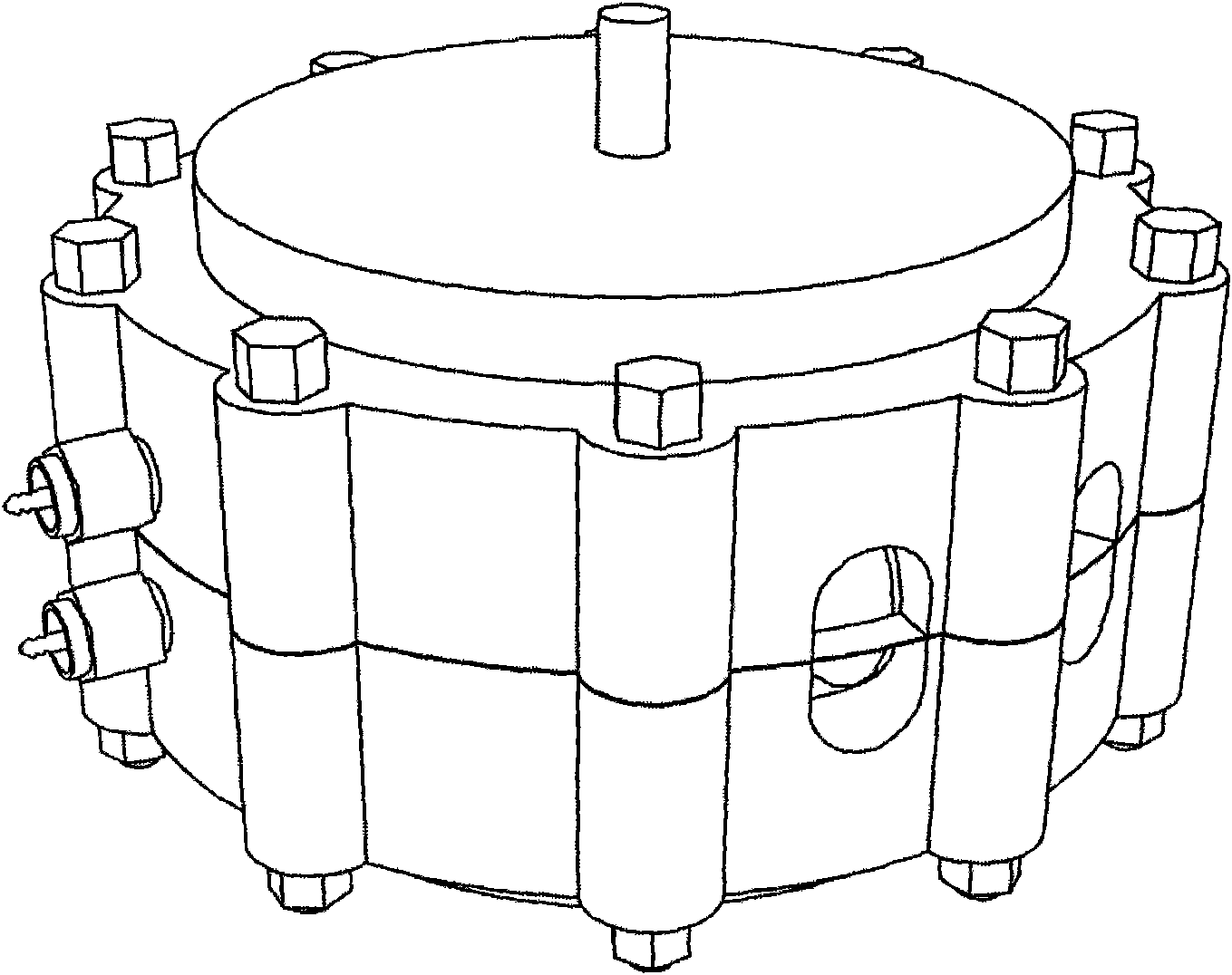
[0036] Such as figure 1 For the style after the installation of the present invention, the whole machine is fixed by bolts on the upper and lower shells, and the rotor is enclosed inside. A glow plug and intake and exhaust valves are arranged on a circle of side walls.
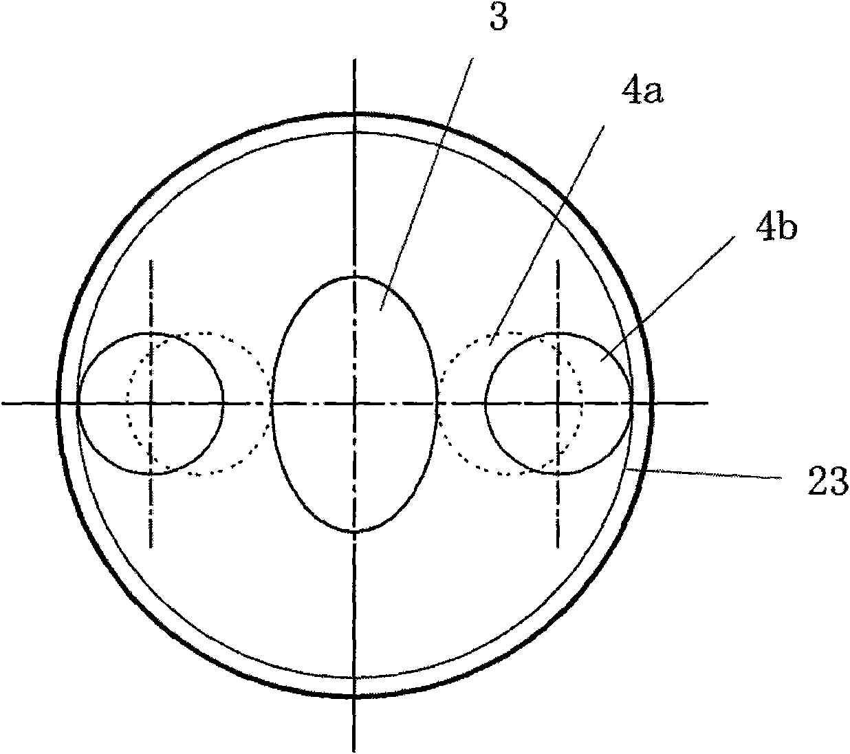
[0037] Such as figure 2 It is a schematic cross-sectional view of the engine. It can be seen from the figure that the output shaft (1) is located at the central axis of the whole machine, and a bearing (2) is sleeved on the output shaft (1), and the bearing (2) is placed on the disc member (5) is inserted into the central hole of the output shaft, so that the two opposite disc members (5) can stably rotate around the output shaft. At both ends of the output shaft (1), there are two oval gears (3) arranged at an angle of 90 degrees. The oval gears are firmly fixed on the output shaft by the output shaft bolts (9) and cannot rotate around the output shaft. On both sid...
PUM
 Abstract
Description
Claims
Application Information