Underwater multi-beam sounding system and method

A multi-beam, detection system technology, applied in radio wave measurement systems, measurement devices, sound wave re-radiation and other directions, can solve the problems of difficult frequency conversion, reduced measurement range, and reduced measurement accuracy, to overcome narrow emission bandwidth, anti-interference and other problems. The effect of ability enhancement and strong anti-interference ability

Inactive Publication Date: 2010-10-06
SOUTH CHINA UNIV OF TECH
View PDF6 Cites 48 Cited by
  • Summary
  • Abstract
  • Description
  • Claims
  • Application Information

AI Technical Summary

Problems solved by technology

But this device has some shortcomings: 1. The device uses single-frequency continuous pulses, and the underwater acoustic channel is a frequency-selective fading channel. The fixed single-frequency signal may encounter a large attenuation, resulting in no echo detection 2. The device uses the signal energy center method to detect the arrival time of the echo. This method estimates the arrival time of the echo by weighted average, so the measured depth value is actually the multi-scattering within the beam irradiation range. Average water depth value of the point
In this way, although the influence of background noise on the measurement can be well reduced, when there are secondary echoes or the beam width is large, and there are many scattered points on the seabed, the time determination method based on median estimation will have a certain degree of measurement accuracy. decline
3. There is a contradiction between the distance resolution and the ranging range. If the depth range of the system measurement is required to be increased, the greater the transmit power of the transducer or the longer the duration of the transmit pulse is required, but the transmit power of the transducer There is an upper limit, if the duration of the transmitted pulse is increased, the distance resolution will decrease
However, the traditional direct-sequence spread spectrum ranging technology has high requirements on the transmission bandwidth, while the transmission bandwidth of ordinary underwater acoustic transducers is relatively narrow. The energy is the largest, so if you want to use the traditional spread spectrum technology in the field of underwater acoustic ranging, the hardware requirements for the underwater acoustic transducer are very high, which increases the cost of the system
In addition, because the ordinary piezoelectric transducer emits mechanical waves through the piezoelectric effect, it has a serious "smearing" phenomenon in the process of generating ultrasonic waves, that is, the piezoelectric wafer needs to go through several vibration cycles to be released. "Start-up vibration" spans to "resonance", and there will be "after-vibration" when the excitation is stopped, which also makes it difficult to use a single transducer to achieve fast frequency conversion
[0007] In summary, the existing underwater multi-beam bathymetry technology mainly has some limitations and deficiencies in the following aspects: (1) The single-frequency signal has poor ability to resist underwater environment interference and is susceptible to frequency-selective fading of underwater acoustic channels (2) The detection of the signal energy center method cannot accurately estimate the arrival time of the first echo; (3) There is a contradiction between the distance resolution and the range of the traditional pulse detection method
In addition, when pseudo-random ultrasonic ranging and spread spectrum ranging are applied to underwater acoustic sounding, the following two problems will be faced: (1) The transmission bandwidth of ordinary underwater acoustic transducers is narrow, and the spectrum expansion capability is limited; ( 2) The phenomenon of "tailing" of the piezoelectric transducer is serious, and the frequency jump is slow

Method used


Image

  • Underwater multi-beam sounding system and method
  • Underwater multi-beam sounding system and method
  • Underwater multi-beam sounding system and method

Examples


Embodiment Construction

[0047] The present invention will be further described in detail through specific embodiments below in conjunction with the accompanying drawings, but the specific implementation and protection scope of the present invention are not limited thereto.

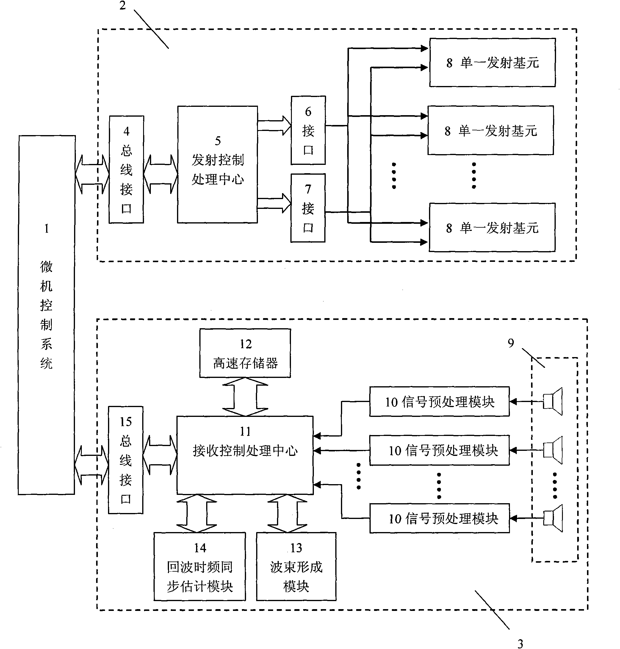
[0048] see figure 1 , The underwater multi-beam detection system in this embodiment is mainly composed of: a microcomputer control system 1 , an acoustic wave transmitting system 2 and an acoustic wave receiving and detecting system 3 . in,

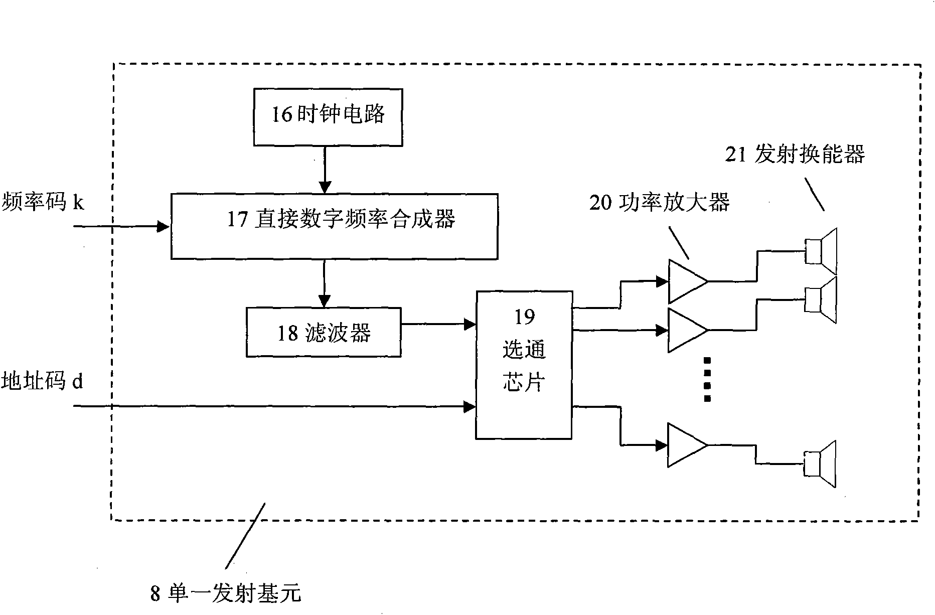
[0049] The sound wave emission system 2 includes a emission control processing center 5, a first interface 6, a second interface 7 and a plurality of single emission units 8; each single emission unit 8 includes a plurality of emission transducers 21 with different resonance frequencies, and The control system 1 is connected to the emission control processing center 5 through the first bus interface 4; the emission control processing center 5 is connected to a plurality of single emission p...


PUM


Abstract

The invention discloses an underwater multi-beam sounding system and a detecting method thereof. The system comprises a microcomputer control system, and a sound wave emission system and a sound wave receiving and detecting system which are connected with the microcomputer control system. The sound wave emission system is provided with a plurality of single emission units, and each single emission unit comprises a plurality of transmitting transducers with different resonance frequencies. The invention also relates to an underwater multi-beam sounding method according to the system. Through two unique modes of 'frequency sweeping and frequency selecting' and 'frequency hopping and sounding', the sounding range resolution is improved by reducing the frequency hopping residence time, the sounding range is increased by increasing the frequency point number of the frequency hopping, and the problem of the contradiction between the range resolution and the sounding range in the single-frequency pulse sounding. The sounding system and the underwater multi-beam sounding method can effectively resist underwater acoustic channel frequency selectivity fading and complex environmental noise, can accurately estimate the first echo reaching time under each wave beam angle, and improve the underwater multi-beam sounding accuracy.

Description

technical field [0001] The invention relates to the technical field of underwater acoustic detection, in particular to an underwater multi-beam detection system and method. Background technique [0002] Since the American scientist Fessenden manufactured the first echo sounder in the early 20th century, underwater acoustic echo sounding has gradually become the main method for measuring underwater topography. The traditional echo sounding method is consistent with the traditional ultrasonic ranging principle. First, the sending transducer emits sound waves vertically downward. The sound waves reach the bottom of the water and are reflected, and then the reflected echo reaches the receiving transducer to be received. According to the estimated delay τ of the echo obtained relative to the emitted sound wave, and the transmission speed of the sound wave in the water υ (known), the water depth is obtained Therefore, the focus of ultrasonic ranging and sounding is to estimate t...

Claims


Application Information

Patent Timeline
Patent Type & Authority Applications(China)
IPC IPC(8): G01S15/08G01S7/539
Inventor 韦岗陈庭柱曹燕宁更新张军
Owner SOUTH CHINA UNIV OF TECH
Why Eureka
Try Eureka