AI technical title is built by PatSnap AI team. It summarizes the technical point description of the patent document.
An aircraft and controller technology, applied in the field of aircraft, can solve problems such as high fuel consumption, difficult landing, and low speed, and achieve the effects of improved maneuverability, low operating cost, and low noise
Inactive Publication Date: 2010-10-13
海口新坤科技有限公司
View PDF6 Cites 18 Cited by
Summary
Abstract
Description
Claims
Application Information
AI Technical Summary
This helps you quickly interpret patents by identifying the three key elements:
Problems solved by technology
Method used
Benefits of technology
Problems solved by technology
[0010] 1. Tilting rotor vertical take-off and landing aircraft is technically complex and difficult, and the workload of maintenance and overhaul is heavy. The rotor has high requirements on the surrounding environment, which is easy to cause safety accidents
[0011] 2. For a vertical take-off and landing aircraft that provides lift and thrust by rotating the engine nozzle, the take-off weight of the aircraft can only be 83%-85% of the engine thrust. This limits the payload of the aircraft and affects the fuel load of the aircraft volume and range
When taking off vertically, the nozzle burns severely on the ground, and the hot air ejected is easy to flow back to the air intake
At the same time, when the aircraft takes off vertically, the engine power is at its maximum, and the fuel consumption is particularly large, which limits the flight radius of the aircraft
[0012] 3. Catapult take-off and landing process are complex, especially at night or in bad weather, it is difficult to land, the requirements for auxiliary systems are high, and the operation and maintenance costs are high
[0013] 4. The vertical take-off and landing aircraft with propellers has high vibration and noise, heavy maintenance workload, high cost of use, low speed and short flight range
When the aircraft is flying and staying, the propeller is easy to spin against the surrounding objects, making the operation of the aircraft and the requirements for the terrain very strict, posing a potential and continuous threat to the safety of the aircraft
Method used
Image
Click on the blue label to locate the original text in one second.
Reading with bidirectional positioning of images and text.
Examples
Embodiment 1
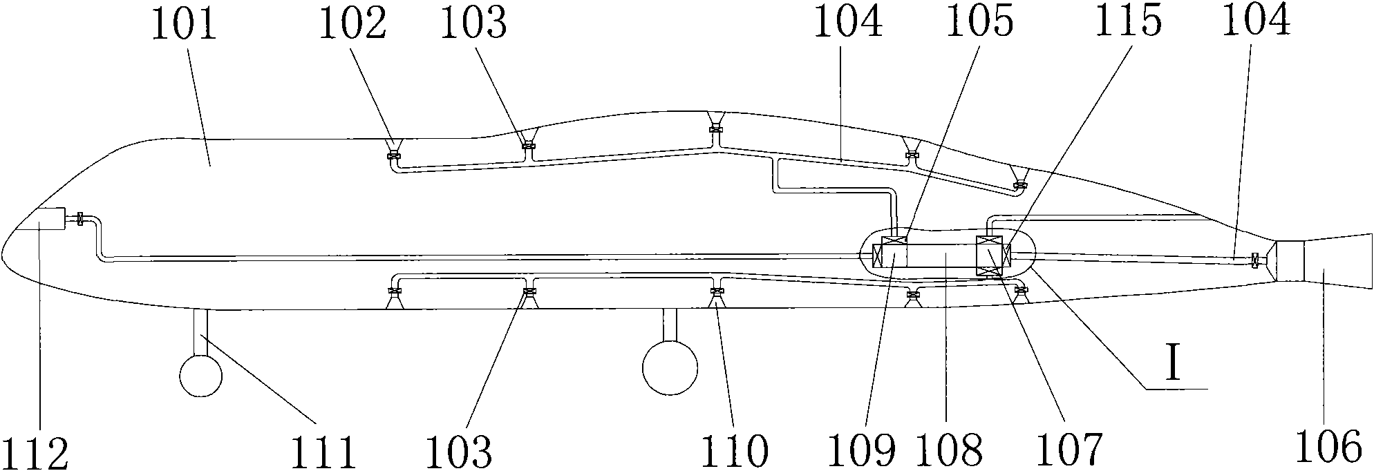
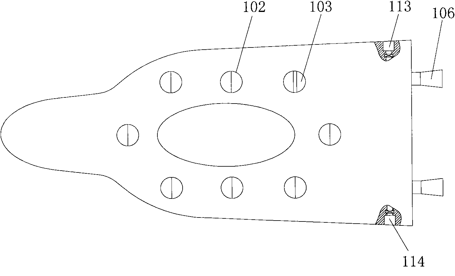
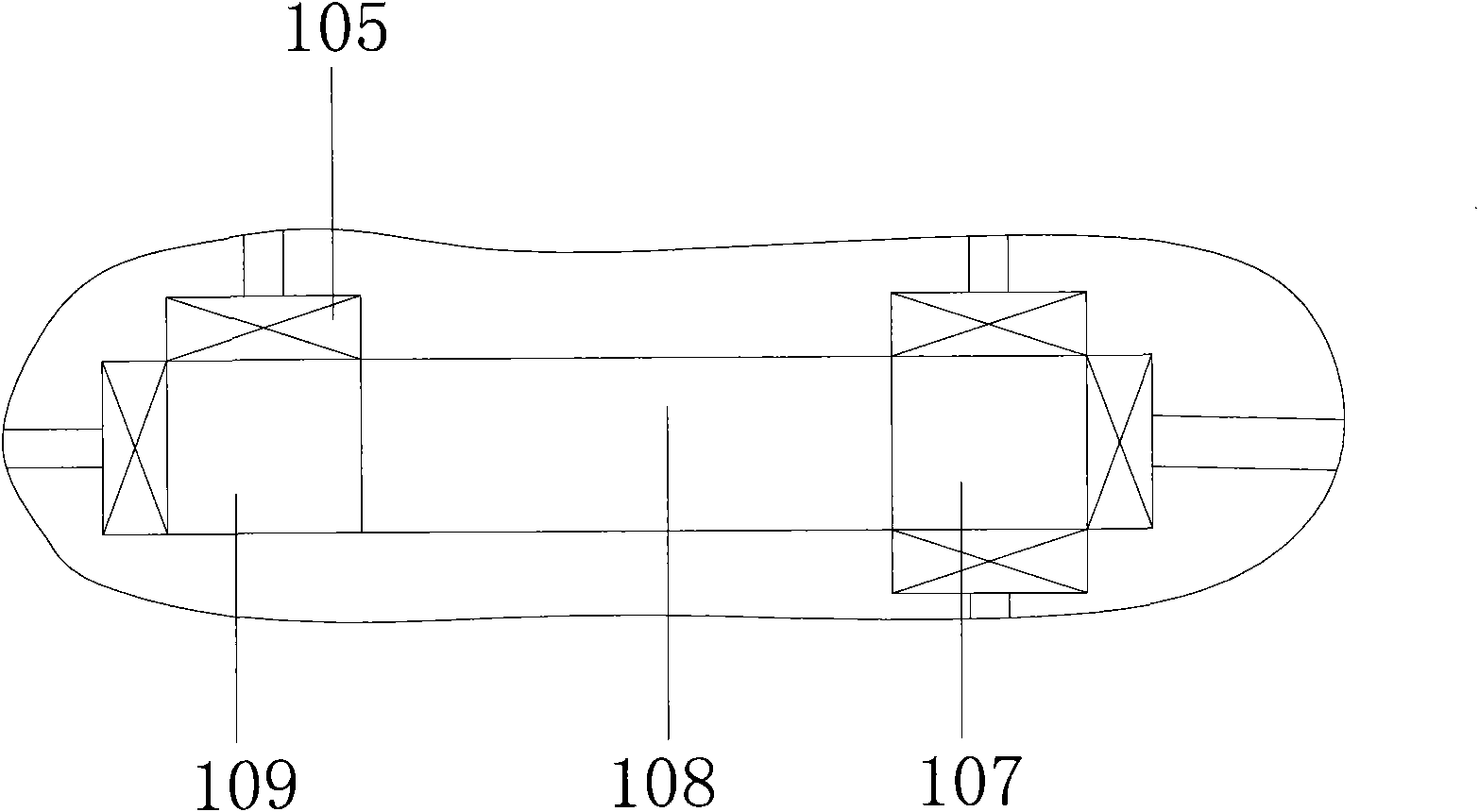
[0072] see Figure 1-Figure 3 , figure 1 It is a schematic structural diagram of the aircraft provided in Embodiment 1 of the present invention, figure 2 for figure 1 top view of image 3 for figure 1 Partial enlarged view of I.
[0073] Wherein, 101 is a fuselage, 102 is an upper air hole, 103 is an air valve, 104 is a trachea, 105 is a first gas valve device, 106 is a tail air hole, 107 is an exhaust box, 108 is an engine, and 109 is an air intake box, 110 is a lower air hole, 111 is a landing gear, 112 is a front end air hole, 113 is a right air hole, 114 is a left air hole, and 115 is a second gas valve device.
[0074] Front, back, left, right, up and down of aircraft provided by the present invention are equipped with front air hole 112, tail air hole 106, left side air hole 114, right side air hole 113, upper air hole 102, lower air hole 110 respectively. Wherein, the front air hole 112 , the left air hole 114 , the right air hole 113 , the upper air hole 102 and...
Embodiment 2
[0100] Multiple engines are installed on the aircraft to independently control the air in and out of different air holes.
[0101] as attached Figure 9 , Figure 10 , Figure 9 It is a schematic structural diagram of the aircraft provided in Embodiment 2 of the present invention, Figure 10 for Figure 9 top view.
[0102] Among them, 201 is the fuselage, 202 is the upper air hole, 3a is the air pipe, 4a is the air valve, 3b is the air pipe, 4b is the air valve, 3c is the air pipe, 4c is the air valve, 3d is the air pipe, 4d is the air valve, 3e is Air pipe, 4e is an air valve, 3f is an air pipe, 4f is an air valve, 5a is a gas valve device, 5b is a gas valve device, 206 is an air intake box, 207 is a first engine, 208 is an exhaust box, and 209 is a lower air hole , 210 is a landing gear, 211 is a front air hole, 212 is a second engine, 213 is an air distributor, 214 is a right jet hole, 215 is a right suction hole, 216 is a third engine, 217 is a tail air hole, and 218...
PUM
Abstract
The embodiment of the invention discloses an aircraft which comprises a fuselage, an engine as well as a front end air hole, a tail air hole, a left side air hole, a right air hole, an upper air hole and a lower air hole which are respectively arranged at the front, at the rear, at the left, at the right, at the upper and at the lower of the fuselage, wherein all the air holes are provided with air valves; and the aircraft also comprises air pipes used for connecting the engine and the air holes, and a controlled used for respectively controlling the flow rate of the air flow in all the air valves. The aircraft utilizes the controller to control the opening and closing of the air valves so as to control air to pass in and out the air holes, thus regulating the work and the power of the engine, reaching the requirements of different elevating forces and thrusts needed by various flight attitudes, and realizing the flight attitudes such as vertical lifting, horizontal flight, hovering, turning and the like of the aircraft. The aircraft can vertically lift in a narrow place, and improves the motility of the aircraft so as to lead the aircraft to move rapidly. The aircraft has low manufacturing and using costs, easy operation, low noise, safety and reliability.
Description
technical field [0001] The invention relates to the technical field of aircraft, and more specifically, relates to an aircraft capable of vertical lift. Background technique [0002] In the past hundred years since the birth of aircraft, the performance has been significantly improved. It not only has the advantages of speed, comfort, safety and reliability, but also is not affected by complex terrain. It has been widely used in civil transportation, scientific research and modern military fields. [0003] Aircraft with vertical take-off and landing capabilities do not require special airports and runways, and can take off and land on very small flat ground, and can also take off on damaged airport runways or airstrips, and have very low requirements for the surrounding environment , generally used in complex environments or areas that cannot be reached by other means of transportation, with high mobility and practicability. [0004] At present, there are four main ways for...
Claims
Application Information
Patent Timeline
Application Date:The date an application was filed.
Publication Date:The date a patent or application was officially published.
First Publication Date:The earliest publication date of a patent with the same application number.
Issue Date:Publication date of the patent grant document.
PCT Entry Date:The Entry date of PCT National Phase.
Estimated Expiry Date:The statutory expiry date of a patent right according to the Patent Law, and it is the longest term of protection that the patent right can achieve without the termination of the patent right due to other reasons(Term extension factor has been taken into account ).
Invalid Date:Actual expiry date is based on effective date or publication date of legal transaction data of invalid patent.

