Sputtering apparatus and film forming method

A technology of sputtering device and film forming method, which is applied in sputtering coating, vacuum evaporation coating, coating, etc., which can solve the problems of increased film thickness, difficulty in obtaining a uniform film, and inability to form a film. , to achieve the effect of high uniformity of film thickness

Inactive Publication Date: 2010-10-13
EBARA-UDYLITE CO LTD
View PDF0 Cites 5 Cited by
  • Summary
  • Abstract
  • Description
  • Claims
  • Application Information

AI Technical Summary

Problems solved by technology

However, even so, the film thickness increases where more sputtering particles are splashed, and it is difficult to obtain a film with satisfactory uniformity
In addition, since the sputtered particles are sputtered with high linearity, there is a problem that film formation cannot be performed on parts other than the surface facing the target material, or only a thin film can be formed.

Method used


Image

  • Sputtering apparatus and film forming method
  • Sputtering apparatus and film forming method
  • Sputtering apparatus and film forming method

Examples


Embodiment Construction

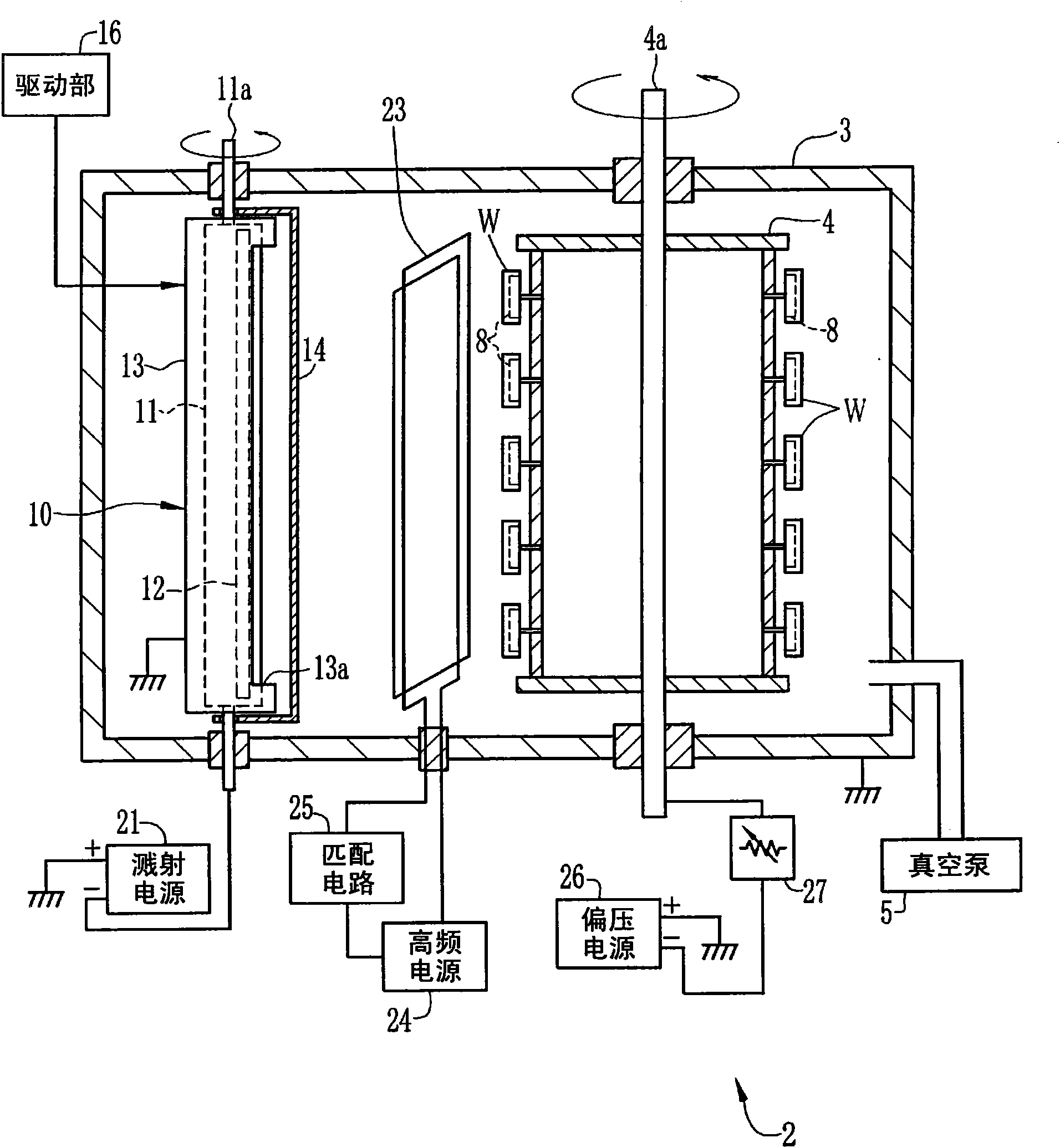
[0041] figure 1 The structure of the sputtering apparatus 2 which implements this invention is shown. The vacuum chamber 3 is, for example, substantially cylindrical in shape made of stainless steel. A cylindrical turntable 4 is disposed inside the vacuum chamber 3 . The turntable 4 is rotatable around a rotating shaft 4a perpendicular to the vacuum chamber 3, and is rotated at a predetermined speed by a motor (not shown).

[0042] A vacuum pump 5 is connected to the vacuum tank 3, and the inside of the vacuum layer 3 is adjusted to a vacuum degree required for sputtering during film formation. In addition, the turntable 4 may be rotated about a horizontal rotation axis. In addition, in order to carry out operations such as loading and unloading of the workpiece W, target replacement, inspection and refurbishment described later, the vacuum chamber 3 is opened by a known structure after leaking to atmospheric pressure.

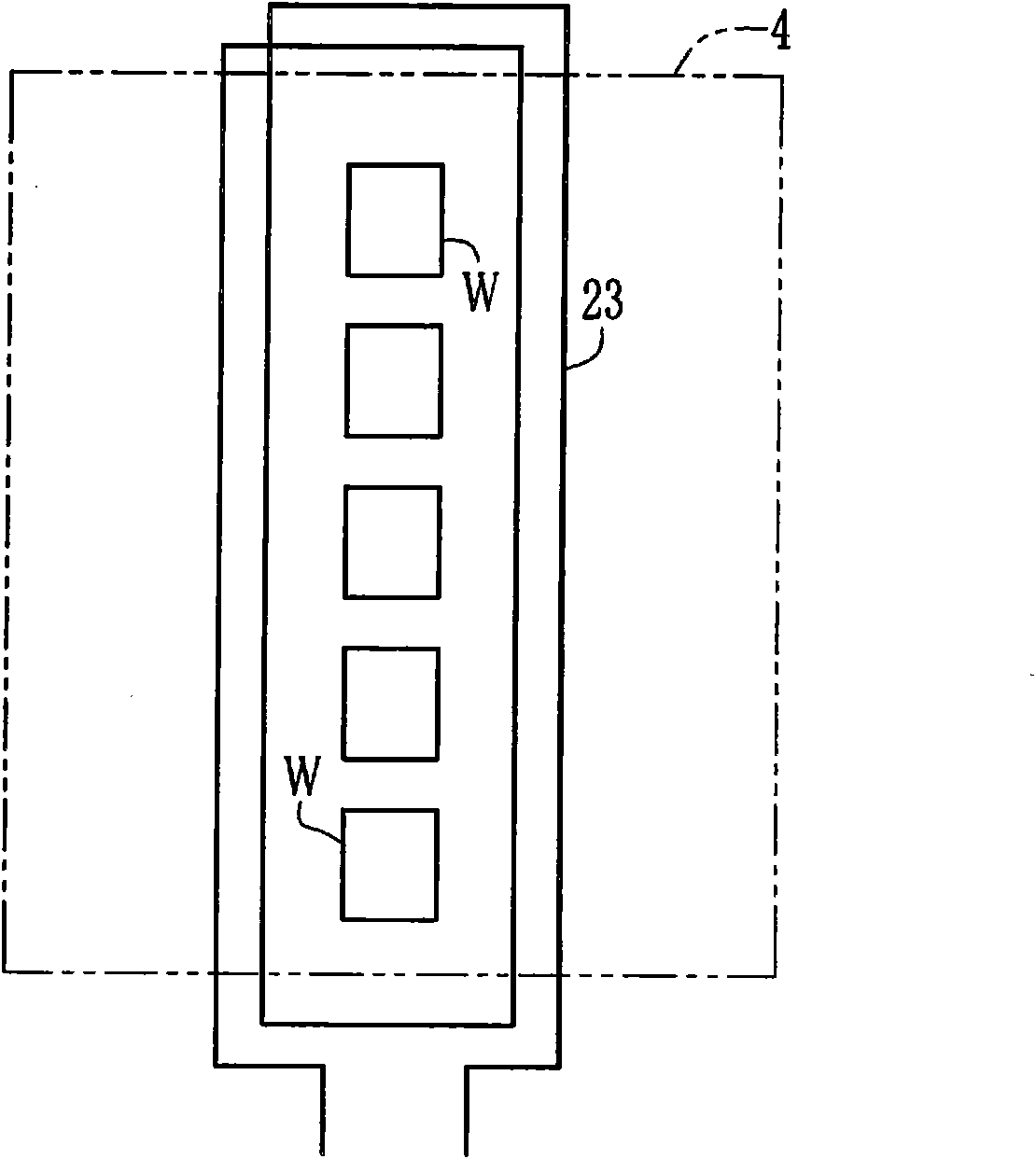
[0043] On the outer peripheral surface of the turnta...


PUM


Abstract

An RF coil (23) is arranged between a target (11) and a work (W), and sputtering particles scattering from the target (11) toward the work (W) are ionized to positive ions when the RF coil (23) is supplied with high frequency power. The work (W) or the work holder (8) holding the work (W) are negatively biased by a bias power supply (26), and the ionized sputtering particles are attracted. A current flowing in the bias power supply (26) is controlled not to have the adhered sputtering particles immediately become electrically neutral.

Description

technical field [0001] The present invention relates to a sputtering device and a film forming method for forming a film on the surface of a workpiece. Background technique [0002] For example, a sputtering device that forms an optical thin film such as an anti-reflection film is often used for decorative coating of a workpiece such as a main body casing of a mobile phone or a door handle of an automobile. In a sputtering device, a vacuum chamber is filled with a thin sputtering gas, and a target material is used as an electrode to perform glow discharge in the vacuum chamber. Then, the positive ions of the plasma generated by the glow discharge collide with the target material to knock out sputtered particles (atoms, molecules) from the target material, and deposit the sputtered particles on the surface of the workpiece to form a thin film. In addition, there is a reactive sputtering method in which a reactive gas such as oxygen or nitrogen is introduced into a vacuum cha...

Claims


Application Information

Patent Timeline
Patent Type & Authority Applications(China)
IPC IPC(8): C23C14/34H01L21/285
CPCC23C14/3471C23C14/345C23C14/34H01L21/285H01L21/20H01L21/02631
Inventor 堀江邦明吉冈润一郎
Owner EBARA-UDYLITE CO LTD
Why Eureka
Try Eureka