Wire-arranging mechanism of multi-head wire-rewinding machine and numerical control wire-arranging method

A wire take-up machine and cable arrangement technology, which is applied in the direction of conveying filamentous materials, thin material processing, transportation and packaging, etc. It can solve the problems of easy damage of travel switches, increased manufacturing costs, and accidents caused by involvement

Inactive Publication Date: 2010-10-20
东莞市康汇聚线材科技有限公司
View PDF5 Cites 13 Cited by
  • Summary
  • Abstract
  • Description
  • Claims
  • Application Information

AI Technical Summary

Problems solved by technology

[0003] The existing two-layer take-up motor corresponds to two horizontal wire rods and two rows of take-up motor controllers. The wires to be rewound in each layer are obliquely pulled from one end of the multi-head wire take-up machine to the wire-laying guide wheel. The following contradictions are difficult to solve: 1) When multiple wires are pulled from the reversing guide wheel to multiple wire guide wheels, the density of the wires is relatively high. In addition to the oblique pulling of the wires, which will partially block the control panel, it may also occur when the wire is broken. Various unexpected situations such as broken ends twisted on other wires, especially when the production speed is high, the mutual interference is more serious; 2) The upper take-up motor interferes with the lower take-up motor, when the upper take-up reel When the wire is broken, if the broken end is not fixed in time, the broken end will slide to the lower layer, and when it touches the wire running near the lower horizontal wire rod or the lower wire take-up reel in operation, it is easy to be entrained and involved and cause an accident; 3) When the wire on any take-up reel is broken, if the take-up motor is not turned off in time, the speed of the take-up motor will be accelerated due to the loss of the limit of the wire tension on its speed, and the radius of rotation of the broken end will increase, thus hitting Hit the upper, lower, left, and right reels, causing a large number of finished wires to be damaged; 4) When the diameters of the reels are different, the position of the wire guide wheel should be adjusted to make it as close as possible to the reel. The existing structure either has no adjustment function, or needs to be adjusted Adjust the cable swing lever corresponding to each take-up motor; 5) There is also a horizontal cable rod and a row of take-up motor controllers between the upper and lower two-layer take-up motors, so a large distance is required, resulting in the upper and lower layers It cannot be located at a good operating height at the same time. Either the upper layer is too high so that the workers cannot use force when going off the assembly line, or the lower layer is too short and the workers need to bend over to operate; The wire arrangement mechanism is a complex three-dimensional structure; 7) The side plate of the wire take-up machine where the wire take-up motor is installed is made of a thicker flat steel plate, because the horizontal wire arrangement rod and the wire arrangement guide wheel occupy a certain space, so that the range of the cable arrangement cannot It is close to the side plate, so the installation position of the take-up reel on the rotation shaft of the take-up motor cannot be close to the end plate of the take-up motor, so that the cantilever of the rotation shaft of the take-up motor will be lengthened, which will adversely affect its rigidity
In addition, the disadvantages of the traditional rack and pinion structure are as follows: 1) After wear and tear, the reversing clearance will be increased, resulting in a long pause time during reversing, which will affect the quality of the cable; 2) Each cable shaft is connected by its own rack and pinion Auxiliary drive, if the consistency of each rack and pinion pair is not good or the actual occlusal radius is different during installation, it will cause the movement speed or stroke of each cable shaft rod to be inconsistent, so that the cable arrangement of each take-up reel is inconsistent and cannot be adjusted; 3) Every The gear power of each rack and pinion pair needs to come from the same motor, and these rack and pinion pairs are distributed in a large three-dimensional space, so a more complicated transmission mechanism is required
[0004] On the other hand, the traditional cable control method is a mechanically adjusted limit switch, and its disadvantages are: 1) It is difficult to grasp the adjustment scale when manually adjusting the position of the limit switch; 2) The limit switch is easily damaged under a large number of repeated mechanical actions, and The repeatability of the trigger position is not high; 3) The adjustment mechanism is more complicated, which not only increases the manufacturing cost, but also increases the maintenance cost
However, although the "Discharging Mechanism of Multi-Head Receiver" (200720061037.0) solved the above problems, it failed to achieve separate control on the left and right sides, and it is difficult to ensure the coaxiality and parallelism of multiple linear bearings when installed. Improve
And "a kind of digital control wiring device and its wiring method" (200710032602.5) has solved the above problems, but it has higher requirements on the hardware of the encoder and PLC, otherwise the pulse signal sent by the encoder to the PLC may be lost, and in the PLC The recorded cable position will deviate, resulting in the overall drift of the cable range

Method used


Image

  • Wire-arranging mechanism of multi-head wire-rewinding machine and numerical control wire-arranging method
  • Wire-arranging mechanism of multi-head wire-rewinding machine and numerical control wire-arranging method
  • Wire-arranging mechanism of multi-head wire-rewinding machine and numerical control wire-arranging method

Examples


Embodiment 1

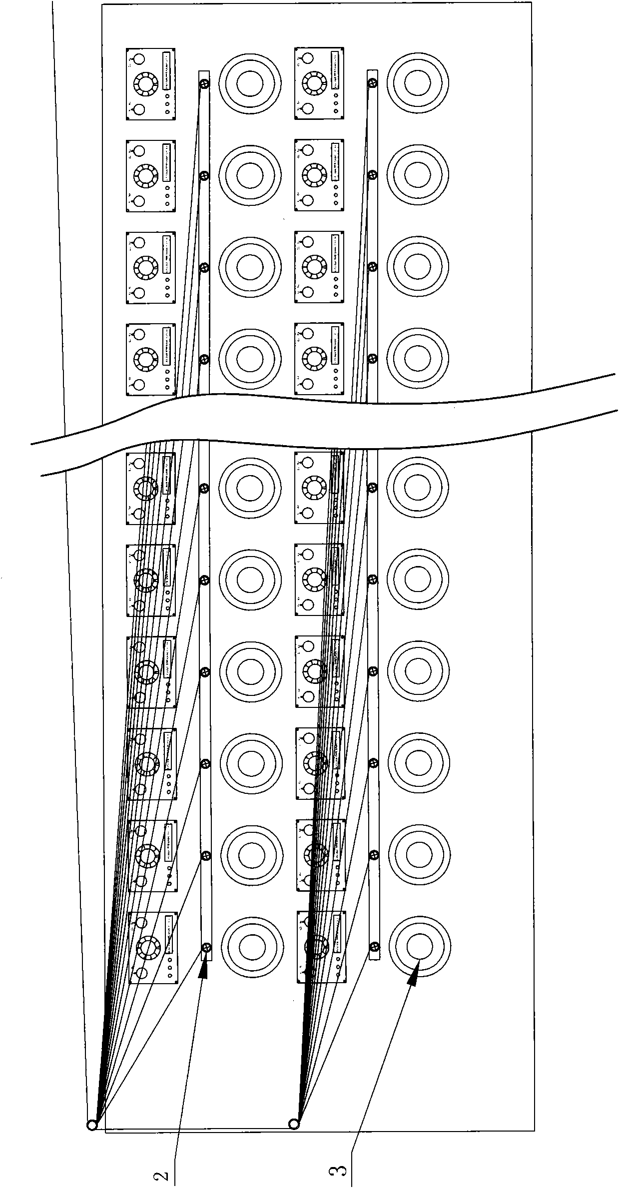
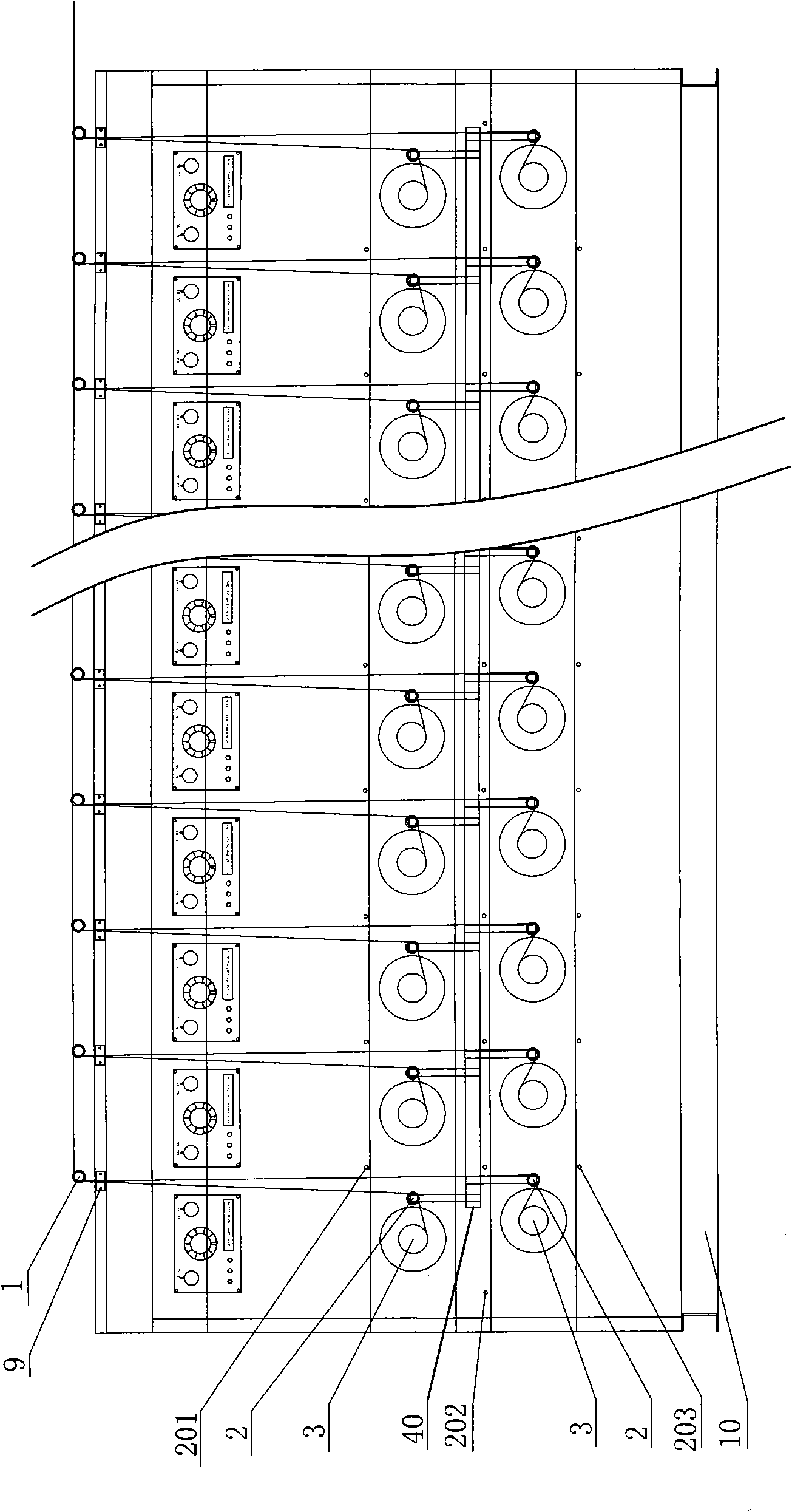
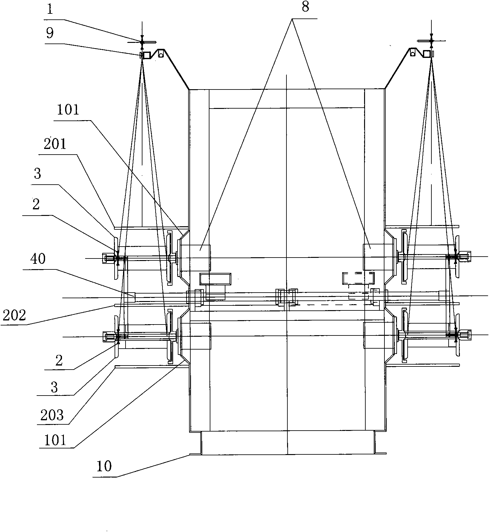
[0129] Embodiment one, such as Figures 2 to 5As shown, a wire arrangement mechanism of a multi-head wire take-up machine, which includes a frame 10 and a PLC controller, the frame 10 is provided with at least one layer of horizontally arranged multiple take-up reels 3, each take-up reel 3 It is driven and connected by a wire take-up motor 8, and also includes a screw drive device, a wire-guiding guide wheel 2 with the same number as the wire-receiving reel 3, a reversing guide wheel 1 with the same number of production heads, and a wire-guiding guide wheel 2 for driving A reciprocating linear guide wheel driving device parallel to the axial direction of the wire take-up reel 3; The wheel 1 is correspondingly arranged above the wire take-up reel 3, and the side of each wire take-up reel 3 is correspondingly provided with a double-bearing non-sway wire guide wheel 2, and the horizontal wire rod 40 is connected to each wire guide wheel 2. The wire-guiding wheel driving device i...

Embodiment 2

[0229] Embodiment two, such as Figure 6 and Figure 7 As shown, the difference from Embodiment 1 is that, in order to better ensure the parallel movement of the horizontal cable rod 40 for the cable arrangement mechanism of the multi-head wire take-up machine, the same constant speed motor 56 can be used to distribute the cables in a triangle. The belt pulley drives two sets of screw mandrel drive units, and the screw mandrel female 51 of two sets of screw mandrel drive units is connected with the cable guide wheel drive unit at two points. After the screw nut 51 is connected with the wire-guiding wheel driving device at two points and separated by a certain distance, it can more effectively limit the deflection when the wire-guiding wheel driving device moves, and ensure its parallel movement. But this will make the structure more complicated, and it is not necessary to use it under normal circumstances. Figure 6 As shown in , the screw nut 51 is located at the top of the...

Embodiment 3

[0230] Embodiment three, such as Figure 8 As shown, the difference from Embodiment 1 is that the wire blocking device is a wire blocking plate 71 . Because the wire retaining rod can only prevent the finished wire rods from being injured on other wire take-up motors 8, the protection of the wire rods during the operation from the reversing guide wheel 1 to the other wire take-up reels 3 near the broken wire take-up reel 3 is not enough, and it will still happen Therefore, the third embodiment adopts the structure of U-shaped wire retaining groove 70 and wire retaining plate 71 instead of the structure of wire retaining rod. Figure 8 Shown is the structure of two-layer take-up reels 3, its U-shaped wire retaining groove 70 and wire retaining plate 71 will not only damage the finished wires on other take-up reels 3, but also will not interrupt other wires running nearby. The wire rod of the take-up reel 3. The three sides of the U-shaped line retaining groove 70 are installe...


PUM


Abstract

The invention relates to the field of wire-arranging technology of a multi-head wire-rewinding machine, in particular to a wire-arranging mechanism of the multi-head wire-rewinding machine and a numerical control wire-arranging method. The wire-arranging mechanism of the multi-head wire-rewinding machine comprises a stander, a PLC controller, a screw rod driving device, wire-arranging guide wheels, a reversing guide wheel and a wire-arranging guide wheel driving device, wherein the wire-arranging guide wheel driving device is connected with the wire-arranging guide wheels; the screw rod driving device comprises a screw rod, a screw rod nut, an approach switch, two screw rod bearing seats, two synchronous belt pulleys, a synchronous belt and a constant speed motor, wherein the screw rod nut is connected with the wire-arranging guide wheel driving device; the PLC controller is connected with the approach switch and the constant speed motor; and the PLC controller is provided with a forward rotation monitoring timer, a reverse rotating monitoring timer, a millisecond-level reversing timer and a speed increasing and reducing timer. The invention not only reduces the interference amongwires and the production accidents and improves the wire-arranging quality and finished product wire quality, but also simplifies the structure, is easy for operation and reduces the manufacturing and maintaining costs.

Description

Technical field: [0001] The invention relates to the technical field of wire arrangement of a multi-head wire take-up machine, in particular to a wire arrangement mechanism and a numerically controlled wire arrangement method of a multi-head wire take-up machine. Background technique: [0002] The multi-head wire take-up machine is widely used in enamelling machines, annealing and tinning machines and other wire production equipment. Its feature is that multiple take-up motors share a wire arrangement mechanism, so it is relatively simple and efficient. Such as figure 1 As shown, it is a schematic diagram of the structure of the position of the existing multi-head wire take-up machine. Usually, the take-up motors of the multi-head wire take-up machine are symmetrically distributed on the left and right sides of the machine, and each side is in the horizontal direction on the thicker flat steel plate. A plurality of take-up motors are distributed, and one or two layers are d...

Claims


Application Information

Patent Timeline
Patent Type & Authority Applications(China)
IPC IPC(8): B65H57/14B65H54/74B65H54/28B65H59/38
Inventor 周开勇
Owner 东莞市康汇聚线材科技有限公司
Why Eureka
Try Eureka