Austenitic heat resistant alloy

A heat-resistant alloy and austenitic technology, applied in lighting and heating equipment, components of steam boilers, steam boiler accessories, etc., can solve problems such as poor bonding and defects

Inactive Publication Date: 2010-10-20
NIPPON STEEL CORP
View PDF12 Cites 25 Cited by
  • Summary
  • Abstract
  • Description
  • Claims
  • Application Information

AI Technical Summary

Problems solved by technology

Therefore, the bondability with the weld metal tends to deteriorate, and defects due to welding workability tend to occur easily.

Method used


Image

  • Austenitic heat resistant alloy
  • Austenitic heat resistant alloy
  • Austenitic heat resistant alloy

Examples


Embodiment

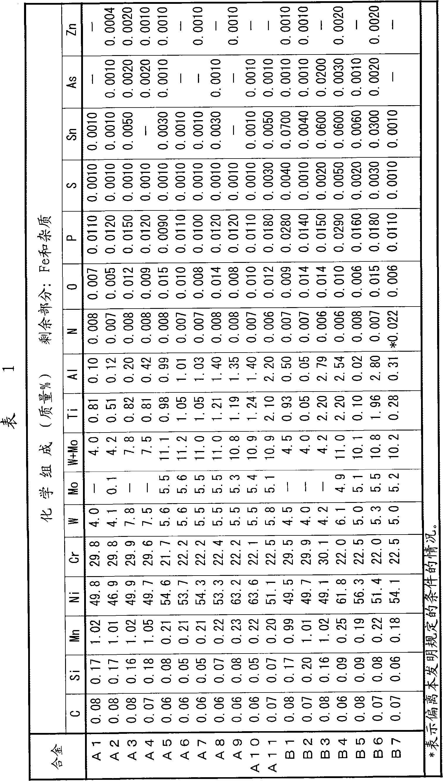
[0154] Austenitic alloys A1 to A11 and B1 to B7 having the chemical compositions shown in Table 1 and Table 2 were melted in a vacuum melting furnace to obtain 50 kg of ingots.

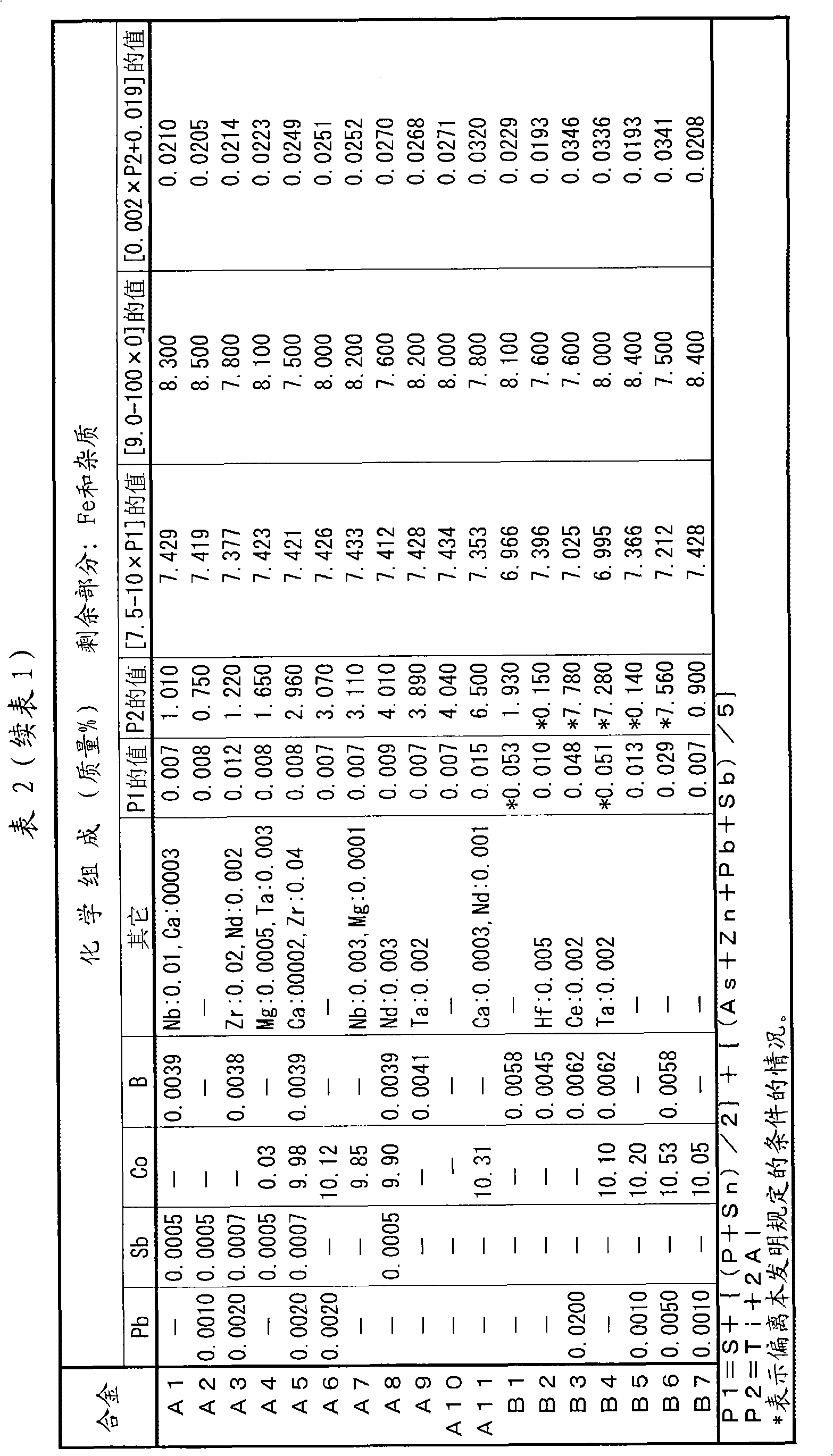
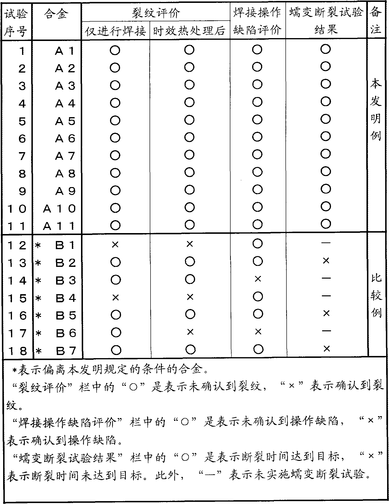
[0155] Alloys A1 to A11 in Table 1 and Table 2 are alloys whose chemical compositions are within the range specified by the present invention. On the other hand, alloys B1 to B7 are alloys whose chemical compositions deviate from the conditions specified in the present invention.

[0156] Table 1

[0157]

[0158] Table 2

[0159]

[0160] The ingot obtained above was manufactured into a plate material having a plate thickness of 20 mm, a width of 50 mm, and a length of 100 mm by hot forging, hot rolling, heat treatment, and machining. In addition, the same ingot was fabricated into a fully homogeneous welding material with an outer diameter of 2.4 mm by hot forging and hot rolling.

[0161] After processing a V-shaped groove with a bottom (root) depth of 1 mm and an angle of 30° along the...


PUM


Abstract

An austenitic heat resistant alloy, which comprises, by mass percent, C<=0.15%, Si<=2%, Mn<=3%, Ni: 40 to 80%, Cr: 15 to 40%, W and Mo: 1 to 15% in total content, Ti<=3%, Al<=3%, N<=0.03%, O<=0.03%, with the balance being Fe and impurities, and among the impurities P<=0.04%, S<=0.03%, Sn<=0.1%, As<=0.01%, Zn<=0.01%, Pb<=0.01% and Sb<=0.01%, and satisfies the conditions [P1=S+{(P+Sn) / 2}+{(As+Zn+Pb+Sb) / 5}<=0.050], [0.2<=P2=Ti+2Al<=7.5-10P1], [P2<=9.0-100O] and [N<=0.002P2+0.019] can prevent both the liquation crack in the HAZ and the brittle crack in the HAZ and also can prevent defects due to welding fabricability, which occur during welding fabrication, and moreover has excellent creep strength at high temperatures.

Description

technical field [0001] The present invention relates to austenitic heat-resistant alloys. Specifically, it relates to an austenitic heat-resistant alloy excellent in weldability used in high-temperature equipment such as boilers for power generation and chemical equipment. Background technique [0002] In recent years, in order to increase efficiency, ultra-supercritical pressure boilers with increased steam temperature and pressure have been newly developed all over the world. Specifically, it is planned to increase the steam temperature from around 600°C to above 650°C, or even above 700°C. This is because of energy saving and efficient use of resources and reduction of CO for environmental protection 2 Gas emissions have become one of the topics to solve energy problems and become an important industrial policy. Furthermore, in the case of boilers for power generation burning fossil fuels, reactor furnaces for chemical industry, and the like, boilers and reactors with ...

Claims


Application Information

Patent Timeline
Patent Type & Authority Applications(China)
IPC IPC(8): C22C19/05C22C30/06
CPCC22C38/54C21D6/001C22C38/002C22C38/44C22C38/04C21D6/004C22C38/50C22C38/06C21D6/002C22C38/008C22C38/02F22B37/04C22C38/52C22C38/001
Inventor 平田弘征伊势田敦朗冈田浩一仙波润之河野佳织宫原整
Owner NIPPON STEEL CORP
Why Eureka
Try Eureka