Side detection-type multipoint touch screen based on frustrated total internal reflection

A technology of suppressed total internal reflection, multi-touch screen, applied in the input/output process of data processing, instruments, electrical digital data processing and other directions, can solve the problems of noise interference, system complexity, infrared light leakage, etc., to avoid interference , the effect of facilitating system integration and reducing the thickness and volume of the system

Inactive Publication Date: 2010-10-20
HEFEI UNIV OF TECH
View PDF4 Cites 9 Cited by
  • Summary
  • Abstract
  • Description
  • Claims
  • Application Information

AI Technical Summary

Problems solved by technology

The ultrasonic method has the advantages of not being affected by temperature and humidity, long service life, good stability, and simple structure, but it is easily disturbed by noises with close or multiplied frequencies, poor multi-point input capability, and high cost
CCD camera method can realize multi-point input and gesture recognition, but usually the system is complex and relatively large
The infrared method is not affected by current, voltage and static electricity, and has a fast response speed and high sensitivity; but it is prone to infrared light leakage, which will interfere with other surrounding optoelectronic devices working in the same band
[0004] Chinese patents CN200810177473.3 and CN200810065714.5 disclose a multi-point touch screen based on frustrated total internal reflection. The technical principle is simple, can effectively avoid light leakage, and reduce interference to surrounding optoelectronic devices, but there are the following technical problems: 1. Currently The bottom surface detection method is adopted, and the entire system is very thick and bulky; 2. CCD is used as the detection device, and the finger touch information is obtained through image processing, which is not conducive to integration

Method used


Image

  • Side detection-type multipoint touch screen based on frustrated total internal reflection
  • Side detection-type multipoint touch screen based on frustrated total internal reflection
  • Side detection-type multipoint touch screen based on frustrated total internal reflection

Examples


Embodiment 1

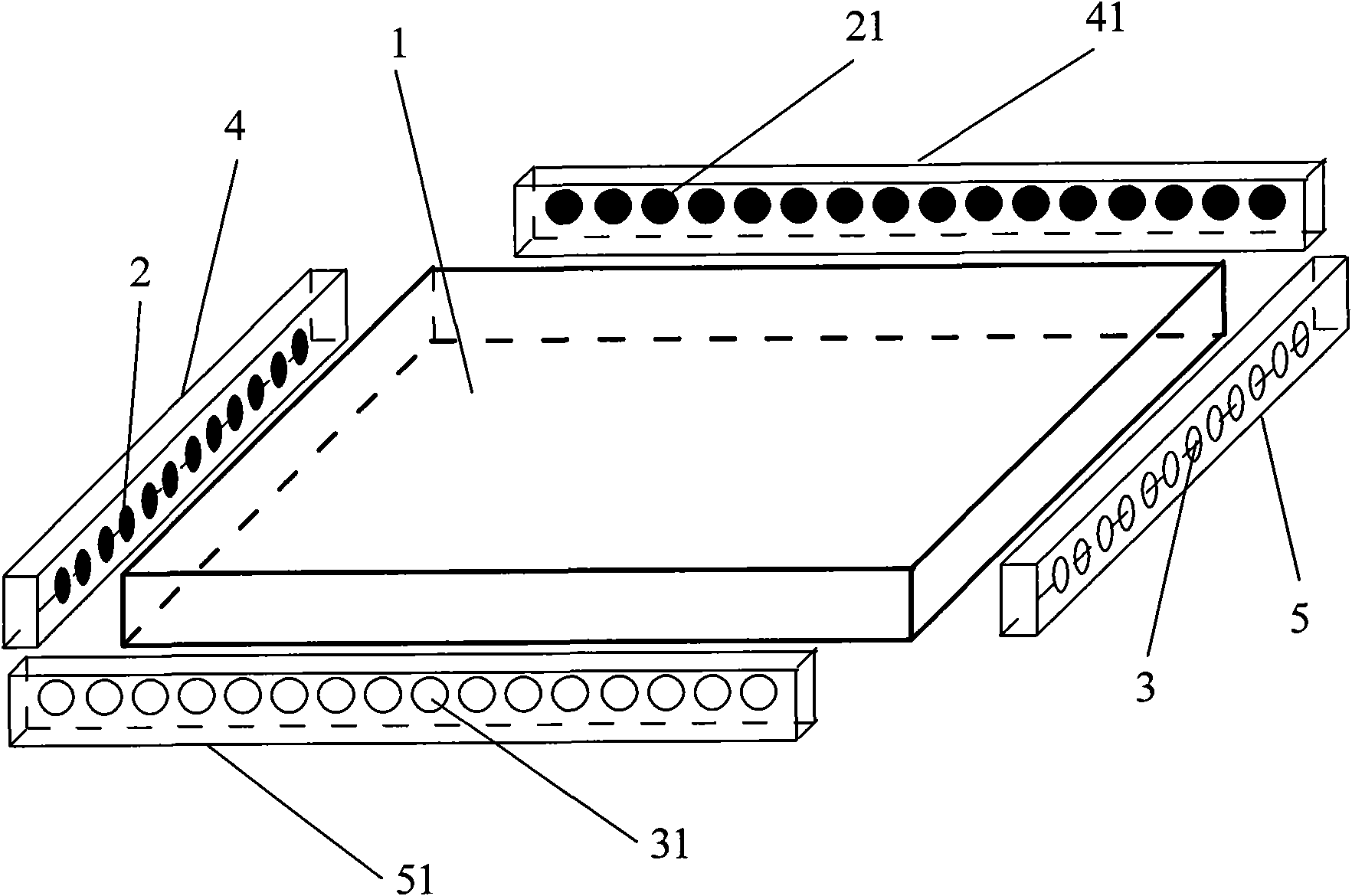
[0025] see figure 1 , the side detection type multi-touch screen based on frustrated total internal reflection includes an optical panel 1 , an LED lamp 2 and a photoelectric receiving tube 3 . The four sides of the optical plate 1 are polished into optical surfaces and form an angle of 90 degrees with the upper and lower surfaces. On the left side of the optical flat panel 1, the left LED lamp 2 is uniformly installed as a light source through the left base plate 4, and the upper LED lamp 21 is uniformly installed on the upper side through the upper base plate 41 as a light source. The left LED lamp 2 and the upper LED lamp 21 are respectively Be fixed in a row on the left bottom plate 4 and the upper bottom plate 41; on the right side, the right photoelectric receiving tube 3 is evenly distributed through the right bottom plate 5, and the lower photoelectric receiving tube 31 is installed on the lower side through the lower bottom plate 51. The photoelectric receiving tubes...

Embodiment 2

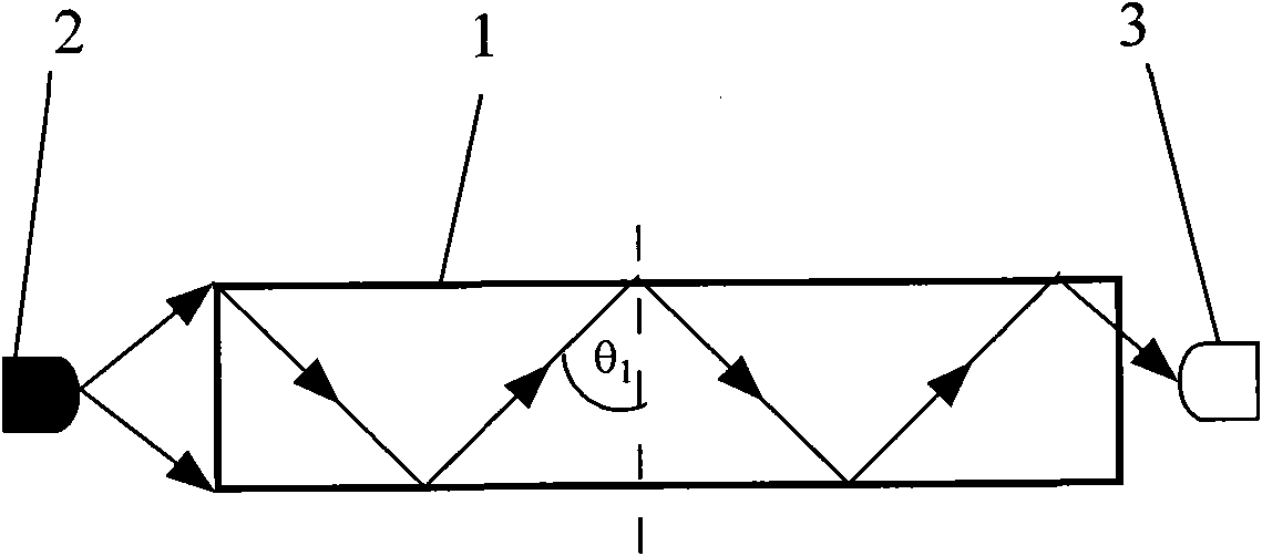
[0032] see Figure 3a , the optical plate 1 is composed of organic optical glass, its upper and lower surfaces are smooth optical surfaces, and the four sides of the optical glass 11 are polished into optical surfaces and form an angle of 45 degrees with the upper and lower surfaces. Install left LED lamp 2 and upper LED lamp 21 on the left side and upper side of optical panel 1, left LED lamp 2 and upper LED lamp 21 adopt visible light band LED, and the optical axis direction of left LED lamp 2 and upper LED lamp 21 is vertical The side of the optical plate 1 forms an angle of 45 degrees with the upper and lower surfaces. The optical axis directions of the right photoelectric receiving tube 3 and the lower photoelectric receiving tube 31 are parallel to the upper and lower surfaces of the optical plate 1 . The transmission of light in the optical flat plate 1 is as Figure 3a and Figure 3b shown. The incident angle of the upper edge light of the left LED lamp 2 on the op...

Embodiment 3

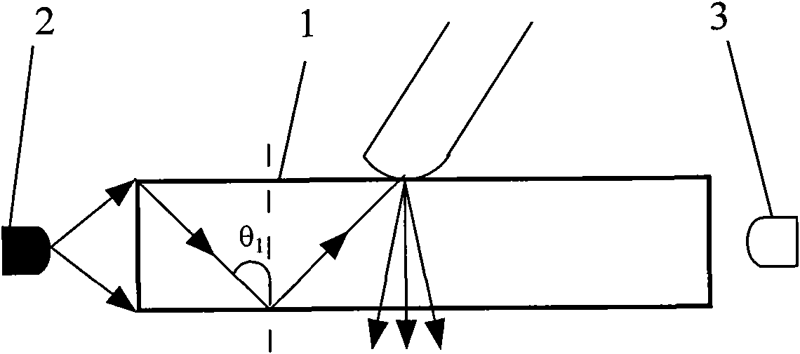
[0036] see Figure 4a , on the basis of Embodiment 1, the optical panel 1 is organic optical glass, and a refractive index matching layer 12 of a polymer material is installed on the touch surface of the optical panel 1 . Its refractive index n 2 and organic optical glass refractive index n 1 Similar, and the hardness of the refractive index matching layer is much lower than that of the organic optical glass, which greatly improves the contact degree between the finger and the optical plate, and enhances the detected touch signal.

[0037] For the case of using optical flat plate 1, such as Figure 4a As shown, assume that the incident angle in the optical plate 1 is θ 1 The transmission angle of the light after the refractive index matching layer and the organic optical glass is refracted is θ 3 , then there is

[0038] no 1 sinθ 1 =n 2 sinθ 3 (3)

[0039] Therefore, according to formula (1), we have

[0040] sin θ ...


PUM


Abstract

The invention relates to a side detection-type multipoint touch screen based on frustrated total internal reflection; four side surfaces of an optical panel of the multipoint touch screen are optical surfaces, LED lamps are uniformly and respectively distributed on the adjacent side surfaces of the optical panel, and the optical axis direction of the LED lamp is vertical to the side surface of the optical panel; opto-electrical receiving tubes are uniformly and respectively distributed on the other two side surfaces of the optical panel correspondingly, the optical axis direction of the opto-electrical receiving tubes is vertical to the side surface of the optical panel; in the invention, LED lamps with infrared light wave band or visible light wave band are used as light sources, and the opto-electrical receiving tubes with the corresponding wave band are used for receiving, the signal of the opto-electrical receiving tube is processed by the circuit to obtain a touch signal, so as to be convenient for system integration. By adopting a side detection mode, the LED light sources and opto-electrical receiving tubes are arranged on the four side surface of the optical panel, so as to realize multipoint touch; meanwhile, light is prevented from being leaked from the optical panel, thereby greatly reducing the thickness and volume of the system.

Description

technical field [0001] The invention relates to a multi-point touch screen, more precisely, it utilizes the principle of frustrated total internal reflection of light to realize a multi-point touch screen with no light leakage, small thickness and high resolution. Background technique [0002] Touch screen technology is currently the most intuitive and convenient input device for human-computer communication. It is a new multimedia interactive device. In some special working environments, it is not suitable to use keyboards and mice as input devices for human-computer interaction. Implementation is a better alternative. In the field of aerospace, pilots can directly issue instructions to the computer system through the touch screen to improve the efficiency of task execution. [0003] There are many technologies that can realize multi-touch, mainly including ultrasonic method, CCD camera method and infrared method. The ultrasonic method has the advantages of not being affe...

Claims


Application Information

Patent Timeline
IPC IPC(8): G06F3/042
Inventor 高伟清吕国强胡跃辉冯奇斌胡俊涛陆红波
Owner HEFEI UNIV OF TECH
Why Eureka
Try Eureka