Protective lens for laser coupling mirror of medical holmium laser therapeutic apparatus

A technology for protecting lenses and treatment machines, applied to lasers, laser components, optics, etc., can solve problems such as fiber damage, long-term maintenance not allowed, laser coupling lens damage, etc.

Inactive Publication Date: 2010-10-20
无锡市大华激光设备有限公司
View PDF5 Cites 3 Cited by
  • Summary
  • Abstract
  • Description
  • Claims
  • Application Information

AI Technical Summary

Problems solved by technology

[0003] Because the fiber is exposed to the air for a long time, the fiber input end is easily polluted, and the contaminated fiber input end will absorb laser energy and be damaged during work, or because the operator did not connect the fiber properly when installing the fiber, and the fiber installation is not in place. The optical fiber will be damaged during the working process, and the damaged optical fiber will cause sputtering. The sputtered glass fiber will damage the laser coupling lens. After the coupling lens is damaged, the laser energy will not be concentrated, and the fiber input end will be damaged again. , resulting in a vicious circle, resulting in a significant attenuation of the output power of the laser
Due to the particularity of the laser optical path, changing the coupling mirror requires recalibrating the optical path, which can only be done in the laser assembly laboratory, and cannot be done on site. This will reduce the utilization rate of the equipment, thereby affecting the use of the equipment, and Because this kind of equipment is used in hospitals, its special conditions do not allow long-term maintenance, so a new protective lens is now used to avoid damage to the coupling lens and reduce unnecessary troubles

Method used


Image

  • Protective lens for laser coupling mirror of medical holmium laser therapeutic apparatus
  • Protective lens for laser coupling mirror of medical holmium laser therapeutic apparatus
  • Protective lens for laser coupling mirror of medical holmium laser therapeutic apparatus

Examples


Embodiment Construction

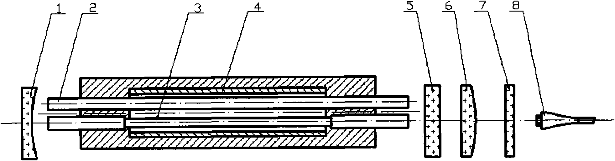
[0011] Depend on figure 1 It can be seen that the interior of the laser is composed of a total mirror 1, a pump xenon lamp 2, a holmium crystal 3, a cavity 4, a half mirror 5, a coupling mirror 6, a protective lens 7, and an optical fiber 8. When a pulse voltage is applied to the pump xenon lamp 2 When the pump xenon lamp 2 emits fluorescence, it is absorbed by the holmium crystal 3 through the reflection inside the cavity 4 to generate stimulated radiation, and then oscillates through the full reflection lens 1 and the half reflection lens 5. When the gain is large enough, the laser light from The output of the half mirror 5 is coupled by the coupling mirror 6 and then enters the optical fiber 8 through the protective mirror 7 for output.

[0012] A protective mirror 7 is placed between the coupling mirror 6 and the optical fiber 8. Both sides of the protective mirror are coated with a 2.1 μm anti-reflection coating. When the laser passes through, there is only a loss of less...


PUM

PropertyMeasurementUnit
Thicknessaaaaaaaaaa

Abstract

The invention discloses a protective lens for a laser coupling mirror of a medical holmium laser therapeutic apparatus. The protective lens comprises a lens body, wherein the lens body is placed between a coupling mirror and an optical fiber; the thickness of a lens per se is only 1mm; an anti-reflection film is plated on the light beam incident surface of the lens; laser basically has no energy loss after passing through the lens; and in the situation that the optical fiber is damaged because of unexpected situations, sputtered impurities are unlikely to adhere to the coupling lens to damage the coupling lens so that the coupling lens is protected. When the optical fiber is damaged because of the unexpected situations, only the optical fiber and the protective lens need replacing without replacing the coupling lens.

Description

technical field [0001] The invention relates to a medical holmium laser treatment machine, in particular to a lens for protecting a laser coupling lens. Background technique [0002] At present, the commonly used medical holmium laser treatment machine equipment does not have a coupling mirror protective lens on it. [0003] Because the fiber is exposed to the air for a long time, the fiber input end is easily polluted, and the contaminated fiber input end will absorb laser energy and be damaged during work, or because the operator did not connect the fiber properly when installing the fiber, and the fiber installation is not in place. The optical fiber will be damaged during the working process, and the damaged optical fiber will cause sputtering. The sputtered glass fiber will damage the laser coupling lens. After the coupling lens is damaged, the laser energy will not be concentrated, and the fiber input end will be damaged again. , resulting in a vicious circle, resulti...

Claims


Application Information

Patent Timeline
IPC IPC(8): H01S3/00A61B18/22G02B1/11G02B1/14
Inventor 王文勇隆林
Owner 无锡市大华激光设备有限公司
Why Eureka
Try Eureka