Piling machine

A technology of pile driver and winch, which is applied in the direction of sheet pile wall, drilling equipment, earthwork drilling and mining, etc. It can solve the problems of slow hole drilling speed, severe drill bit jumping, and inability to guarantee hole quality, etc., and achieves easy jacking of punched steel The effect of the search

Active Publication Date: 2013-03-06
李恩怡
View PDF0 Cites 2 Cited by
  • Summary
  • Abstract
  • Description
  • Claims
  • Application Information

AI Technical Summary

Problems solved by technology

For rock formation operations, it is a necessary requirement for important engineering pile rock-socketing, but the drilling machine for rotary drilling cannot meet the requirements. Because the drill bit is centered and the rock formation is slightly weathered, the drilling is very slow, and the drill bit jumps violently, and the drill bit wears seriously. It is almost impossible to carry out; and the hammer punching operation can completely change this state, the impact operation can be adapted to almost all strata, but when the impact operation is performed on the soil layer, the hole-forming footage speed is much slower than the drilling speed
Due to the existence of the above technical defects, there are defects such as long construction period and low construction efficiency
[0003] And in the prior art, no matter the power transmission of the drilled pile driver or the punched pile driver is a mechanical transmission, using a gearbox and a transmission shaft, so if the speed is to be changed, it is necessary to stop and shift gears to complete. There are boulders, pebbles, and rock formations, which will cause the system to be cut suddenly, causing damage to the transmission system parts, which is not conducive to operation and construction; because the mechanical transmission is restricted by the weight and diameter of the hammer, when punching, it is often necessary to punch a small hole first. hole, and then punch a large hole, reciprocating many times to form, neither the quality of the hole nor the construction period can be guaranteed

Method used


Image

  • Piling machine
  • Piling machine
  • Piling machine

Examples


Embodiment Construction

[0043] The preferred embodiments of the present invention are described below with reference to the accompanying drawings, which are used as a part of this specification to illustrate the principle of the present invention through the embodiments, and other aspects, features and advantages of the present invention will become clear at a glance through the detailed description.

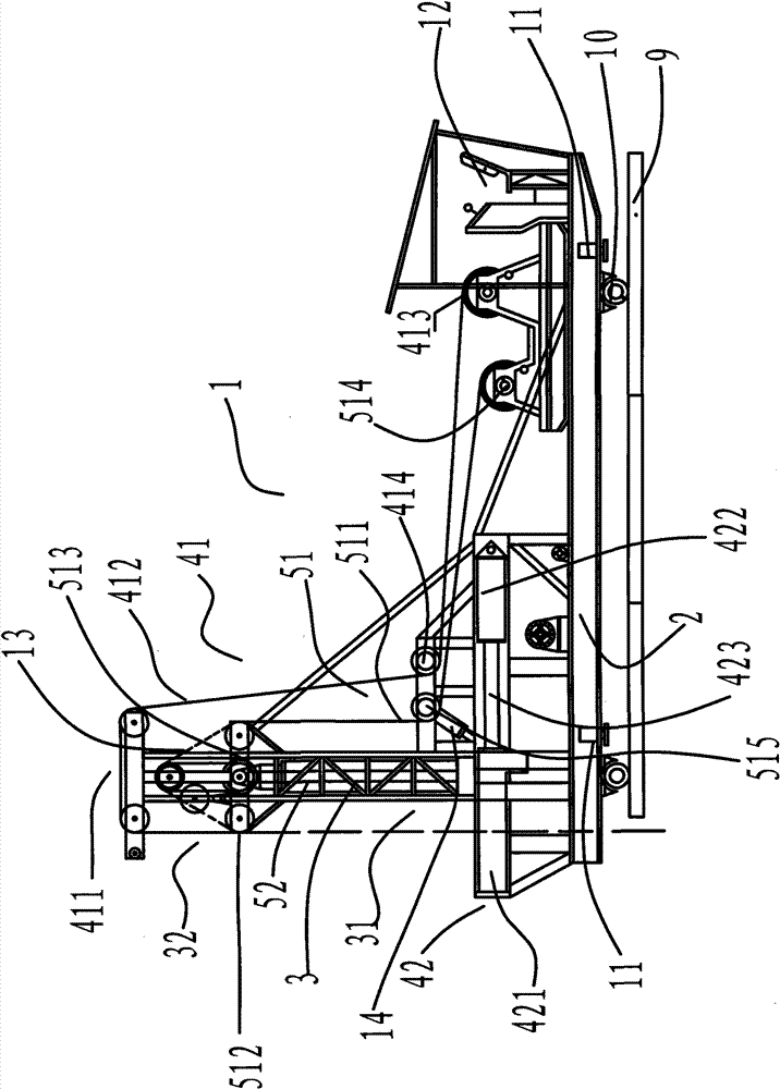
[0044] figure 1 The structural representation of a kind of pile driver provided by the present invention, as figure 1 As shown, a pile driver 1 provided by the present invention includes a chassis 2 and a tower 3 vertically arranged on the chassis 2 , wherein the tower includes a tower base 31 and a tower top 32 . The bottom of the chassis 2 is evenly provided with pipes 10 (seamless steel pipes) front and back, and the chassis 2 is connected to the sleepers 9 at the bottom through the pipes 10; When adjusting the position of the pile driver or adjusting the level of the pile driver, the piston rod of...


PUM


Abstract

The invention provides a piling machine, which comprises drilling equipment for drilling, punching equipment for punching and a drilling turnplate device arranged on a chassis, wherein the drilling turnplate device comprises a drilling turnplate which is driven by hydraulic pressure and is expandable; a punching transmission device comprises a cross beam arranged on a tower and a pulley block arranged on the cross beam; the cross beam is divided into a front movable cross beam and a rear fixed cross beam; the front movable cross beam is hinged with the rear fixed cross beam and can rotate around the point of intersection between the front movable cross beam and the rear fixed cross beam; the pulley block comprises a front guide pulley arranged on the front movable cross beam and a rear guide pulley arranged on the rear fixed cross beam; and the punching equipment comprises a hydraulic jacking device for jacking a punching steel rope in the punching transmission device. The piling machine realizes drilling and punching functions, improves working efficiency and shortens construction period.

Description

technical field [0001] The invention relates to a mechanical equipment for forming holes on land, water, bridges, industrial, civil buildings and engineering piles, in particular to a dual-purpose hydraulic hole-forming pile machine capable of drilling and punching. Background technique [0002] Drilled pile driver and punched pile driver in the prior art, drilled pile driver can only drill holes, and punching machine can only punch holes. For rock formation operations, it is a necessary requirement for important engineering pile rock-socketing, but the drilling machine for rotary drilling cannot meet the requirements. Because the drill bit is centered and the rock formation is slightly weathered, the drilling is very slow, and the drill bit jumps violently, and the drill bit wears seriously. It is almost impossible to carry out; and the hammer punching operation can completely change this state, and the impact operation can be adapted to almost all strata, but when the impa...

Claims


Application Information

Patent Timeline
Patent Type & Authority Patents(China)
IPC IPC(8): E21B6/00E21B6/08E02D5/34
Inventor 李恩怡
Owner 李恩怡
Why Eureka
Try Eureka