Small rotor-type submersible pump

A rotor-type, submersible pump technology, applied in the field of positive displacement pumps, can solve the problems of small impeller outlet width, poor casting process, and low cost, and achieve the effects of expanding the scope of use, no pulse of water flow, and simple structure

Inactive Publication Date: 2010-10-27
余文凌
View PDF10 Cites 15 Cited by
  • Summary
  • Abstract
  • Description
  • Claims
  • Application Information

AI Technical Summary

Problems solved by technology

[0002] At present, the known submersible pumps are centrifugal submersible pumps. This kind of pump has simple structure, few parts and low cost, so the market has a huge amount, but its efficiency is low, especially the efficiency of small centrifugal submersible pumps is extremely low. For example, China Machinery The efficiency formulated in the industry standard JB / T 8902-96 "Small Submersible Electric Pump", the pump with an hourly flow rate of 1.5 tons and a head of 7 meters has an efficiency of 14.2%, an hourly flow rate of 3 tons and a head of 8 meters The efficiency of the pump is 21.9%. It can be seen that the efficiency is extremely low. It is an energy-consuming product. The reason is that the specific speed of the pump is small. For centrifugal pumps, small specific speed and low efficiency are inherent fatal flaws. Problems that have not been overcome so far; In addition, the impeller outlet width of small centrifugal submersible pumps is small, the casting process is poor, the blade passage surface in the impeller is rough, and it is easy to be blocked by water plants, screw shells, impurities, etc., and it is easy to burn the motor in serious cases; for centrifugal For the disadvantages of submersible pumps, it is one direction to replace centrifugal pumps with positive displacement pumps, because the efficiency of positive displacement pumps is generally 60%-90%. Patent CN87100461.A proposes a "piston positive displacement submersible pump", but this The motor part of the pump is still above the liquid level, so it can only be regarded as a submerged pump, not a submersible pump; patent 89203158.1 proposes a "screw submersible electric pump". Compared with the centrifugal submersible pump, the efficiency of the screw submersible pump is improved. However, under the high-speed operation of the submersible motor, the universal coupling of the screw pump is easily damaged, and the stator made of rubber is sensitive to sundries and is easy to wear. In addition, the pump body composed of the transmission box and the screw box is large in size, High cost and limited use; patent ZL93203998.7 "a submersible pump" is an axial piston pump with inlet and outlet check valves, sensitive to impurities in water, not suitable for water, only suitable for oil; patent ZL200520114706.7 "A Steel Wire Cable Type Electric Submersible Permanent Magnet Linear Reciprocating Pump" and Publication No. CN1563715.A "Electric Submersible Permanent Magnet Linear It is used to transport oil products; ZL98238153.0 "rib valve submersible pump" has a rotor-type structure, but it is large in size and complex in structure, and ball bearings are installed in many places inside, which is only suitable for oil pumping; public number CN101054968.A "hydraulic pumping "Oil pump" is a piston reciprocating structure, but its power is hydraulic. Therefore, it is large in size, complex in structure, and requires a hydraulic power source. It is difficult to promote it in small submersible pumps.

Method used


Image

  • Small rotor-type submersible pump
  • Small rotor-type submersible pump
  • Small rotor-type submersible pump

Examples


Embodiment Construction

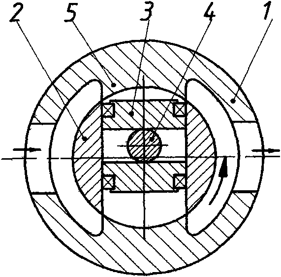
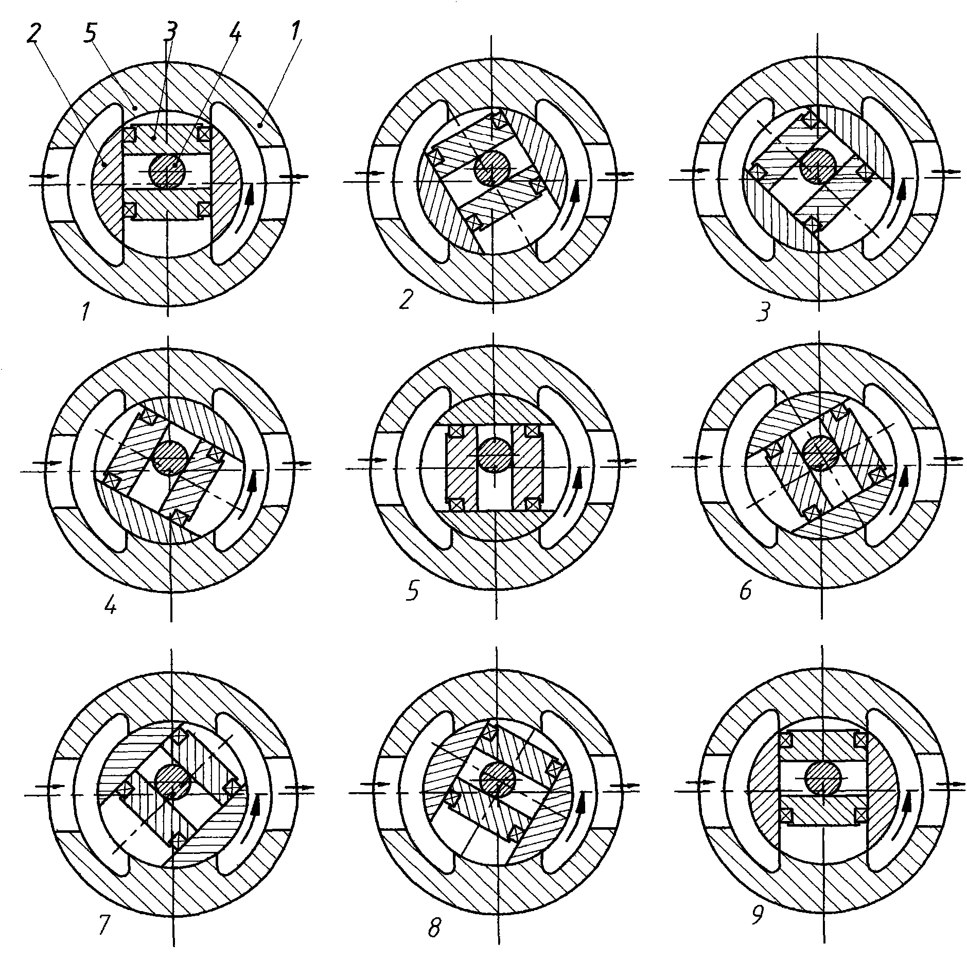
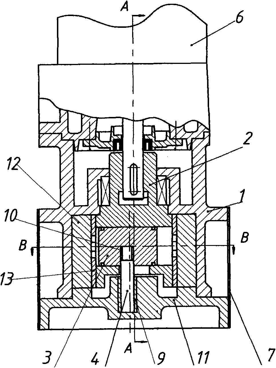
[0036] image 3 , Figure 4 , Figure 5Represents the first embodiment of a small rotor submersible pump, as shown in the figure, 1 is the pump body, 2 is the rotor, 3 is the piston, 4 is the eccentric shaft, 5 is the tongue on the tongue sleeve 13, and 6 is the submersible Motor, 7 is the filter, 8 is the shaft seal device, 9 is the bearing, 10 is the rolling ring, 11 is the pump seat, 12 is the tongue sleeve, 13 is the rotor sleeve.

[0037] In this embodiment, a pair of partition tongues 5 on the partition tongue cover 13 divide the inner cavity of the pump body 1 into a suction chamber and a discharge chamber. The width of the partition tongue 5 is equal to the width of the radial channel on the rotor sleeve 13. When the submersible motor 6 When the rotor 2 is driven to rotate, the piston 3 also rotates. Since the piston 3 is restricted by the eccentric shaft 4, it makes a relative reciprocating motion along the radial through hole during the rotation process, resulting ...


PUM


Abstract

The invention relates to a small rotor-type submersible pump suitable for operation under liquid, which is formed by a pump body, a volute tongue bush, a rotor, a rotor bush, a piston, an eccentric shaft, a pump base, a filter screen and a submersible motor. The invention uses the principle of an eccentric mechanism to realize the reciprocating motion of the piston. When the submersible motor drives the rotor to rotate, the piston rotates around the eccentric shaft while the piston makes reciprocating motion and thereby liquid is drawn in and drained. Under the high-speed rotation, the piston drains liquid two times per turn and thereby the liquid flow output is stable, no pulse is caused, the vibration is low and the noise is low; and moreover, the volume is small, the number of parts is small, the cost is low, the hydraulic loss and the volumetric loss are small, the efficiency is above 70 percent and the pump is a high-efficiency energy-saving product for replacing a centrifugal submersible pump. Moreover, the pump has the good self-absorption performance and the wide runner of a displacement pump and can be used for delivering water liquid and pumping viscous liquid such as petroleum and liquid containing fibrous impurities and particle impurities, and thereby the application scope of the pump is widened.

Description

technical field [0001] The invention relates to a positive displacement pump, especially a small rotor type submersible pump suitable for underwater operations. Background technique [0002] At present, the known submersible pumps are centrifugal submersible pumps. This kind of pump has simple structure, few parts and low cost, so the market has a huge amount, but its efficiency is low, especially the efficiency of small centrifugal submersible pumps is extremely low. For example, China Machinery The efficiency formulated in the industry standard JB / T 8902-96 "Small Submersible Electric Pump", the pump with an hourly flow rate of 1.5 tons and a head of 7 meters has an efficiency of 14.2%, an hourly flow rate of 3 tons and a head of 8 meters The efficiency of the pump is 21.9%. It can be seen that the efficiency is extremely low. It is an energy-consuming product. The reason is that the specific speed of the pump is small. For centrifugal pumps, small specific speed and low e...

Claims


Application Information

Patent Timeline
Patent Type & Authority Applications(China)
IPC IPC(8): F04C2/344F04C15/00
Inventor 余文凌
Owner 余文凌
Why Eureka
Try Eureka