Medium resonator antenna with reconfigurable directional diagram and phased array thereof

A technology of dielectric resonant antenna and pattern, which is applied in the field of large-angle scanning phased array, can solve the problems of inability to radiate electromagnetic energy, large reflection coefficient of the array, and inability to radiate energy to the entire space area, so as to greatly expand the beam scanning angle, The effect of high gain stability and reduced sidelobe level

Inactive Publication Date: 2010-10-27
UNIV OF ELECTRONIC SCI & TECH OF CHINA
View PDF3 Cites 28 Cited by
  • Summary
  • Abstract
  • Description
  • Claims
  • Application Information

AI Technical Summary

Problems solved by technology

In order to expand the target search range of the radar system and the capacity of the communication system, the scanning angle range of the phased array antenna needs to cover the whole space, but due to the characteristics of the microstrip antenna itself, the scanning angle of the existing microstrip phased array is limited by two There are two constraints: one is that due to the existence of mutual coupling between antenna elements, when the antenna array scans within a certain angle range close to the end-fire direction, t

Method used


Image

  • Medium resonator antenna with reconfigurable directional diagram and phased array thereof
  • Medium resonator antenna with reconfigurable directional diagram and phased array thereof
  • Medium resonator antenna with reconfigurable directional diagram and phased array thereof

Examples


Embodiment 1

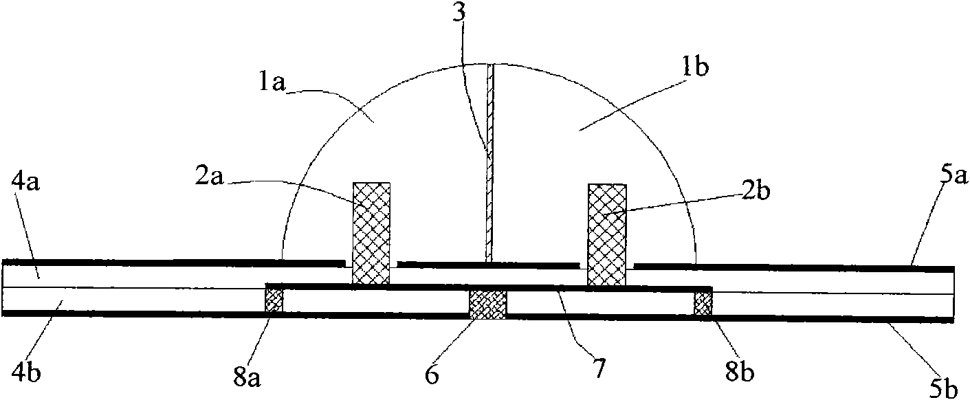
[0041] A pattern reconfigurable dielectric resonant antenna, such as figure 1 , 2 Shown, including radiator and feed structure.

[0042] The radiator includes a dielectric constant ε 1 =6, two 1 / 4 dielectric spheres with a radius of 7.2mm: the first 1 / 4 dielectric sphere 1a and the second 1 / 4 dielectric sphere 1b; two monopole antennas with a radius of 0.7mm and a height of 3.8mm : a first monopole antenna 2a and a second monopole antenna 2b; a metal baffle 3 with a radius of 7.2mm. Two 1 / 4 dielectric spheres are close together to form a dielectric hemisphere, with a metal baffle 3 sandwiched in the middle; two monopole antennas are mirror-symmetrically wrapped in the 1 / 4 dielectric sphere relative to the metal baffle 3, And the leakage bottom end is electrically connected with the feed structure.

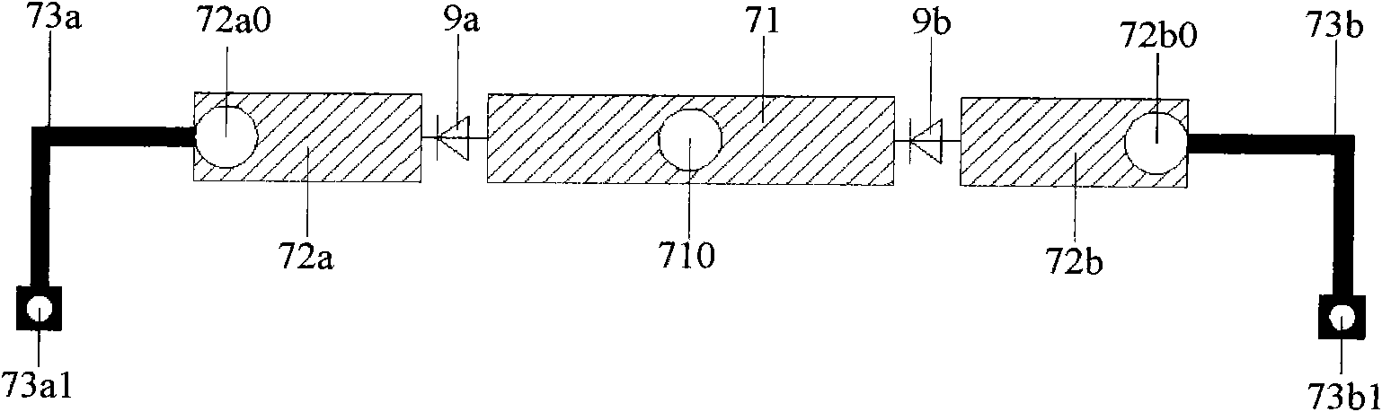
[0043] The feed structure includes a feed circuit support layer and a feed circuit, wherein the feed circuit support layer includes two layers of dielectric constant ε 2 =2, a...

Embodiment 2

[0052] A pattern reconfigurable dielectric resonant antenna phased array, such as Figure 6 As shown, the pattern reconfigurable dielectric resonant antenna provided by N embodiment 1 is composed of antenna units; N pattern reconfigurable dielectric resonant antenna units form a linear phased array, and the n+1th antenna unit The distance x between the geometric center of and the geometric center of the first antenna element n for:

[0053] x n = Σ 1 N - 1 d n = L r - 1 ( r n - 1 N - 1 - 1 )

[0054] Among ...


PUM

PropertyMeasurementUnit
Radiusaaaaaaaaaa
Radiusaaaaaaaaaa
Heightaaaaaaaaaa

Abstract

The invention relates to a medium resonator antenna with a reconfigurable directional diagram, and a phased array thereof, which belong to the technical field of antennas. The radiator of the medium resonator antenna with the reconfigurable directional diagram comprises two monopole antennas capable of working independently, one metal baffle and a high-dielectric constant medium hemisphere covered on the baffle; and a feeding structure adopts a coaxial feed microstrip circuit and a PIN switching diode to realize the simultaneous input of a DC PIN switch control signal and a radio frequency signal and the switching of the working states of the monopole antennas. The phased array of the antenna is a linear phased array consisting of a plurality of the medium resonator antennas with the reconfigurable directional diagrams as antenna units. The medium resonator antenna with the reconfigurable directional diagram has the characteristics of adjustable radiation directional diagram and working frequency; and the phased array of the antenna has the characteristics of the adjustable radiation directional diagram and working frequency, can realize beam scanning in a lager angle and reduce the sidelobe level of a scanning directional diagram, and the gain of the scanning directional diagram is basically unchanged with the increasing of a scanning angle.

Description

technical field [0001] The invention belongs to the technical field of antennas, and relates to an antenna with a reconfigurable pattern and a large-angle scanning phased array formed thereof. Background technique [0002] At present, various wireless systems have higher and higher requirements on performances such as capacity, function, and bandwidth. Obviously, improving system capacity, increasing system functions, and expanding system bandwidth can meet actual needs, but the price paid is that the number of information subsystems carried on the same wireless system platform will increase. It will inevitably increase accordingly, which will lead to negative effects such as increased cost, increased volume, and enhanced electromagnetic compatibility of the entire wireless system. In this context, the reconfigurable antenna has been developed rapidly, which integrates the functions of multiple antennas into the same antenna aperture, and can obtain the actual required ante...

Claims


Application Information

Patent Timeline
IPC IPC(8): H01Q1/36H01Q13/08H01Q19/00H01Q15/23H01Q21/00G01S7/02
Inventor 肖绍球丁卓富柏艳英王秉中
Owner UNIV OF ELECTRONIC SCI & TECH OF CHINA
Why Eureka
Try Eureka