
Optical power meter technology-based method for detecting interface bonding state of laser scratch

A technology of an optical power meter and a detection method, which is applied to measurement devices, instruments, mechanical devices, etc., can solve the problems such as the inability to establish the laser power and the strength of the film base, the inability to make accurate judgments on the critical position, and the failure and damage of the film base interface. To achieve the effect of intuitive display, reliable detection results, and easy observation and analysis

Inactive Publication Date: 2010-11-03
JIANGSU UNIV
View PDF5 Cites 4 Cited by
  • Summary
  • Abstract
  • Description
  • Claims
  • Application Information

AI Technical Summary

Problems solved by technology

Compared with the traditional contact scratching method, this method has the advantages of clear scratch mechanism, direct detection of samples, non-contact measurement, and wide application range, but it also has such advantages as: the equipment is more cumbersome, and it is impossible to establish a complete The relationship between the laser power and the strength of the film base, and the inability to accurately determine the critical position of the film-base interface failure and damage, etc.

Method used


Image

  • Optical power meter technology-based method for detecting interface bonding state of laser scratch
  • Optical power meter technology-based method for detecting interface bonding state of laser scratch
  • Optical power meter technology-based method for detecting interface bonding state of laser scratch

Examples


Embodiment Construction

[0031] specific implementation plan

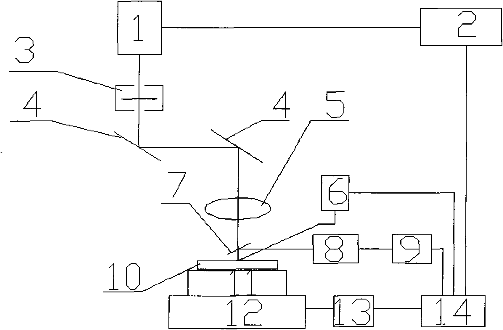
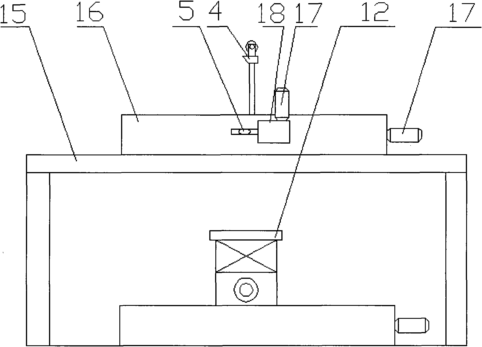
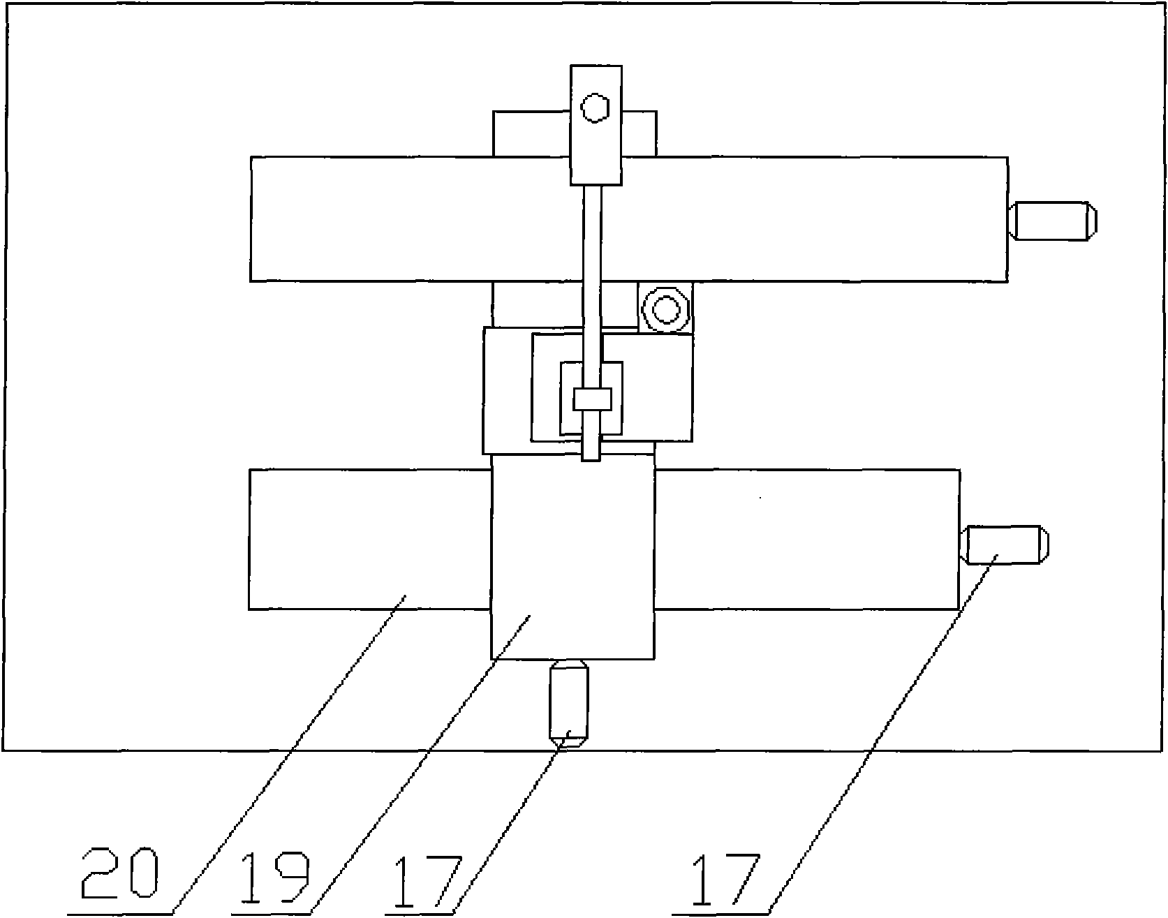
[0032] Depend on figure 1 Shown is a schematic diagram of the long-pulse infrared laser scratch and detection device, figure 2 and image 3It is the front view and top view of the workbench system. The semiconductor laser source 1 emits continuous infrared laser light which passes through the laser beam expander and collimation system 3 to make the laser beam in the direction of the slow axis of the laser more collimated, and then the laser beam passes through the mirror 4 to change the beam direction by 90 degrees. The light beam of 4 converges at one point after passing through the converging lens 5 fixed on the one-dimensional electronically controlled translation platform 18, and this point directly acts vertically on the support supported by the bracket 15 after passing through the mirror 4 fixed on the one-dimensional electronically controlled translation platform 16 On the two-dimensional electronically controlled translation p...


PUM

PropertyMeasurementUnit
thicknessaaaaaaaaaa
diameteraaaaaaaaaa

Abstract

The invention discloses an optical power meter technology-based method for detecting the interface bonding state of a laser scratch and relates to the technical field of laser detection and material performance detection. In the method, the intensity change of reflected light on a loading point of a coating under laser loading is detected by using an optical power meter on line and in real time so as to obtain the critical point of an interfacial failure and interface bonding intensity is represented by a laser power parameter corresponding to the critical point. A measure result is laser quasi-static loading, so that the critical value of coating (membrane) stripping is less than a dynamic measured value and is closer to a practical interface bonding intensity.

Description

technical field [0001] The device of the invention relates to the technical field of laser detection and material performance detection, and in particular refers to a laser scratch device for detecting the combined strength of the film-base interface and the coating interface. An optical power meter is used to detect the reflection of the coating at the loading point under laser loading in real time on-line. The change of light intensity obtains the critical point of interface destruction. Background of the invention [0002] Coating technology is an important advanced technology for surface treatment and material compounding. Its core is to ensure that the coating has good bonding performance with the substrate during the service life. Aiming at the problem of measuring the bonding strength of coating-substrate, domestic and foreign scholars have carried out a series of researches, and proposed a variety of bonding strength detection methods such as scratch method, indentat...

Claims


Application Information

Patent Timeline
Patent Type & Authority Applications(China)
IPC IPC(8): G01N19/04
Inventor 冯爱新孙淮阳曹宇鹏徐传超
Owner JIANGSU UNIV
Learn More