Manufacturing method and system of radio frequency self-adhesive label

A manufacturing method and label technology, applied in semiconductor/solid-state device manufacturing, record carriers used by machines, instruments, etc., can solve the problems of complex radio frequency self-adhesive label manufacturing process, poor adaptability to durable environment, and high manufacturing cost. Achieve the effects of reducing the number of rewinding and unwinding, low dependence, and reducing material costs

Active Publication Date: 2013-02-13
浙江龙游道明光学有限公司
View PDF0 Cites 0 Cited by
  • Summary
  • Abstract
  • Description
  • Claims
  • Application Information

AI Technical Summary

Problems solved by technology

[0017] The purpose of the present invention is to provide a radio frequency self-adhesive label manufacturing method to solve the technical problems of complex radio frequency self-adhesive label manufacturing process, high manufacturing cost, low yield, poor durability and environmental adaptability in the prior art
[0018] Another object of the present invention is to provide a radio frequency self-adhesive label manufacturing system to solve the problems of complex radio frequency self-adhesive label manufacturing process, high manufacturing cost, low yield, durability and poor adaptability to the environment in the prior art. technical problem

Method used


Image

  • Manufacturing method and system of radio frequency self-adhesive label
  • Manufacturing method and system of radio frequency self-adhesive label
  • Manufacturing method and system of radio frequency self-adhesive label

Examples


Embodiment Construction

[0049] Hereinafter, the present invention will be described in detail with reference to the drawings.

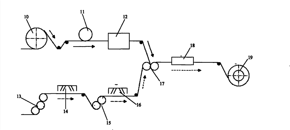
[0050] See figure 2 , Which is a schematic structural diagram of the radio frequency adhesive label manufacturing system of the present invention. The system includes a printer 10, a chip mounting device 11, a testing device 12, a silicone oil coating head 13, a UV curing lamp with a nitrogen protection device 14, and a hot melt Glue coating head 15, UV lamp 16, composite equipment 17, die cutting equipment 18 and winding equipment 19, printing machine 10, chip mounting equipment 11, testing equipment 12, composite equipment 17, die cutting equipment 18 and winding equipment 19 The silicone oil coating head 13, the ultraviolet curing lamp 14 with nitrogen protection device, the hot melt adhesive coating head 15 and the ultraviolet lamp 16 are connected in sequence, and the ultraviolet lamp 16 is connected to the composite equipment 17.

[0051] In this example, the printing mach...


PUM


Abstract

The invention relates to a manufacturing method and a system of a radio frequency self-adhesive label, and the manufacturing method of the radio frequency self-adhesive label comprises the following steps: a) using conductive ink to print an antenna on an inner layer of a surface material film of a thin film; b) mounting a chip; c) testing an electronic device; d) coating silicone oil on the surface of a release material substrate; e) curing a silicone oil release layer; f) coating hot melt adhesive on the silicone oil release layer; g) curing the hot melt adhesive; h) compounding the tested electronic device layer with the release layer coated with the adhesive; i) carrying out die cutting and waste discharge; and j) taking up and obtaining a finished product which can be stuck automatically or manually. The manufacturing method of the radio frequency self-adhesive label can meet the technical requirements of the market on the radio frequency self-adhesive label, has significant advantages in the aspects of manufacturing efficiency, product yield, durability and economy, and can solve the shortcomings of the existing process, and the popularization of the manufacturing method of the radio frequency self-adhesive label is conductive to the wide applications of the radio frequency technology.

Description

Technical field [0001] The present invention relates to the field of radio frequency (RFID) self-adhesive label (electronic label) manufacturing, in particular to a radio frequency self-adhesive label manufacturing method and system. Background technique [0002] RFID (Radio Frequency Identification) is a non-contact automatic identification technology that can automatically identify target objects and obtain relevant data through radio frequency signals. The earliest application of radio frequency identification technology can be traced back to the Second World War, used to automatically and quickly identify both enemy and our aircraft. By the 1970s, the US government used RFID technology for civilian use through the LosAlamos Science Laboratory. By the 1980s, several companies in the United States and Europe began to produce RFID tags. Nowadays, RFID technology has been widely used in various fields. Typical applications include: logistics and supply management, manufacturing...

Claims


Application Information

Patent Timeline
Patent Type & Authority Patents(China)
IPC IPC(8): G06K19/077H01L21/50H01L21/56H01L21/48H01L21/00
Inventor 吴军华
Owner 浙江龙游道明光学有限公司
Why Eureka
Try Eureka