
Integrated extrusion molding equipment

An extrusion molding and equipment technology, applied in the field of integrated extrusion molding equipment, can solve the problems affecting product output efficiency, product uniformity, accuracy and cleaning are difficult to guarantee, screw replacement process is difficult, etc., to facilitate replacement and repair. , the effect of improving utilization and avoiding security problems

Inactive Publication Date: 2010-11-10
SHANGHAI YI CHEN INFORMATION TECH DEV
View PDF2 Cites 10 Cited by
  • Summary
  • Abstract
  • Description
  • Claims
  • Application Information

AI Technical Summary

Problems solved by technology

[0007] 1. Long strip materials need to be cut, while traditional equipment uses mechanical knives for cutting, and its accuracy and cleanliness are difficult to guarantee
[0008] 2. The screw of the traditional screw extruder is directly placed in the cavity with an oval or circular cross-section. During the re-extrusion and conveying process, the material tends to accumulate in some parts, thereby reducing the extrusion effect
[0009] 3. And because there are often accumulations in the screw cavity, these accumulations that have not been fully squeezed for a long time will condense into blocks after a period of time, which will affect the overall product output efficiency and product uniformity, and need to be cleaned frequently
However, the screw replacement process of the traditional twin-screw extruder is difficult, and after the shutdown, the screws will still produce mechanical rotation due to the interlocking structure, which is likely to cause accidents

Method used


Image

  • Integrated extrusion molding equipment
  • Integrated extrusion molding equipment
  • Integrated extrusion molding equipment

Examples


Embodiment Construction

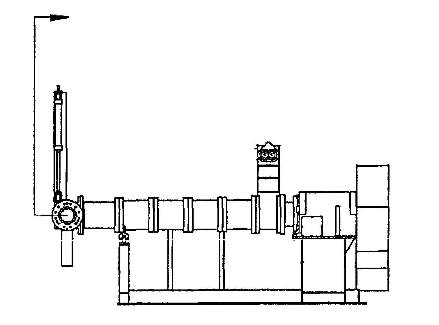
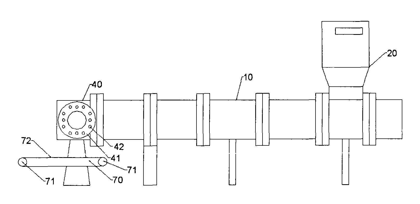
[0041] See attached image 3 and attached Figure 4 , is a horizontal flowchart of the extrusion molding equipment of the present invention and a top view of the equipment. Including a feeding device (20), a screw extruder (10), an extrusion die (40), a cutting device (30), a rotary motor box (50), wherein the feeding device (20) has a flow rate The feeding funnel of control valve and monitoring device; Described screw extruder (10) comprises the cavity that screw rod is installed, support strut, and a plurality of screw rods that mutually hermetically engage with cavity inside; Described extruding mold (40) There are two extrusion disks (41), the extrusion disks are in the shape of a truncated cone, and the extrusion ports are distributed on the outer ring surface of the disk. The material enters the screw extruder (10) through the feeding device (20). In the screw extruder, there is a twin-screw or multi-screw structure to carry out horizontal extrusion and conveying, and ...


PUM


Abstract

The invention provides integrated extrusion molding equipment, which comprises a feeding device (20), a screw extruder (10), an extrusion die (40), a rotary motor box (50), a coating device, a conveying device (70) and a cut-off device (90) in turn. The screw extruder (10) comprises a plurality of screws which are closed and occluded one another; the extrusion die (40) has two extrusion discs (41); the conveying device (70) comprises a driving roller and a conveyor belt (72) with adhesiveness; and the cut-off device (90) is arranged between the adjacent conveyor belts, and comprises a jet orifice (91) and high-pressure jet (92) emitted from the jet orifice to cut strip continuous materials (200) into sectional materials (210) with fixed lengths. The sectional treatment of the extrusion molding materials is realized through the conveying device with height fall and a high-pressure water jet system, products with specified lengths can be accurately obtained, and the cutting process is clean and safe.

Description

technical field [0001] The invention relates to an integrated extrusion molding equipment, in particular, it is an equipment for processing pre-mixed rice flour balls or dough by using a screw extruder and matching devices for extrusion, coating, cutting, etc., which belongs to food processing technology field. Background technique [0002] With the increasing requirements for food nutrition, cereal products with various complex nutrients and their production methods are also developing rapidly. From the early acid pre-steaming process, direct soaking method and coating method, etc. Up to now, it is relatively complete: from grain crushing→pretreatment→mixing with nutrients→extrusion→molding→drying→screening→rice blending in proportion, and finally obtain the technological process of nutrient-enhanced compound grains. [0003] The extrusion-forming step is an important link in the production process. Generally, a single-screw or twin-screw extruder is used to extrude the hy...

Claims


Application Information

Patent Timeline
Patent Type & Authority Applications(China)
IPC IPC(8): A23P1/12A21C11/20A23L7/10A23P30/20B29C48/04B29C48/05B29C48/41B29C48/415B29C48/525
CPCB29C47/6043B29C47/0011B29C2947/92638B29C47/40B29C47/34B29C47/6056B29C47/30B29C47/6012B29L2031/731B26F3/004B29C2793/009A23P1/12B29C47/0014B29K2105/251B29C47/0066B29C2793/0027B29C2947/92933A23L1/10A23P30/20A23L7/10B29C48/05B29C48/04B29C48/0022B29C48/345B29C48/355B29C48/56B29C48/57B29C2948/92638B29C2948/92933B29C48/41B29C48/415B29C48/525
Inventor 刘英
Owner SHANGHAI YI CHEN INFORMATION TECH DEV
Learn More