Electro-optical distance measurement device

A technology of photoelectric ranging and measuring light, which is applied in the direction of measuring devices, measuring devices, measuring distances, etc., can solve the problems of reducing the ranging ability of photoelectric ranging devices, difference frequency interference components, electrical interference, etc., to avoid errors, The effect of simplifying the structure and avoiding electrical interference

Inactive Publication Date: 2010-11-10
NANJING CHERVON IND
View PDF1 Cites 3 Cited by
  • Summary
  • Abstract
  • Description
  • Claims
  • Application Information

AI Technical Summary

Problems solved by technology

[0004] The problem with the above-mentioned phase-type photoelectric distance measuring device is that the initial frequency signal and the low-frequency signal generated in the MCU microprocessor 12' are modulated into a frequency modulation signal in the quadrature modulator 13' and an additional frequency is generated These additional frequency signals cause difference frequency interference on the circuit board inside the photoelectric ranging device and electrical interference between components, thus greatly reducing the ranging capability of the photoelectric ranging device

Method used


Image

  • Electro-optical distance measurement device
  • Electro-optical distance measurement device
  • Electro-optical distance measurement device

Examples


Embodiment Construction

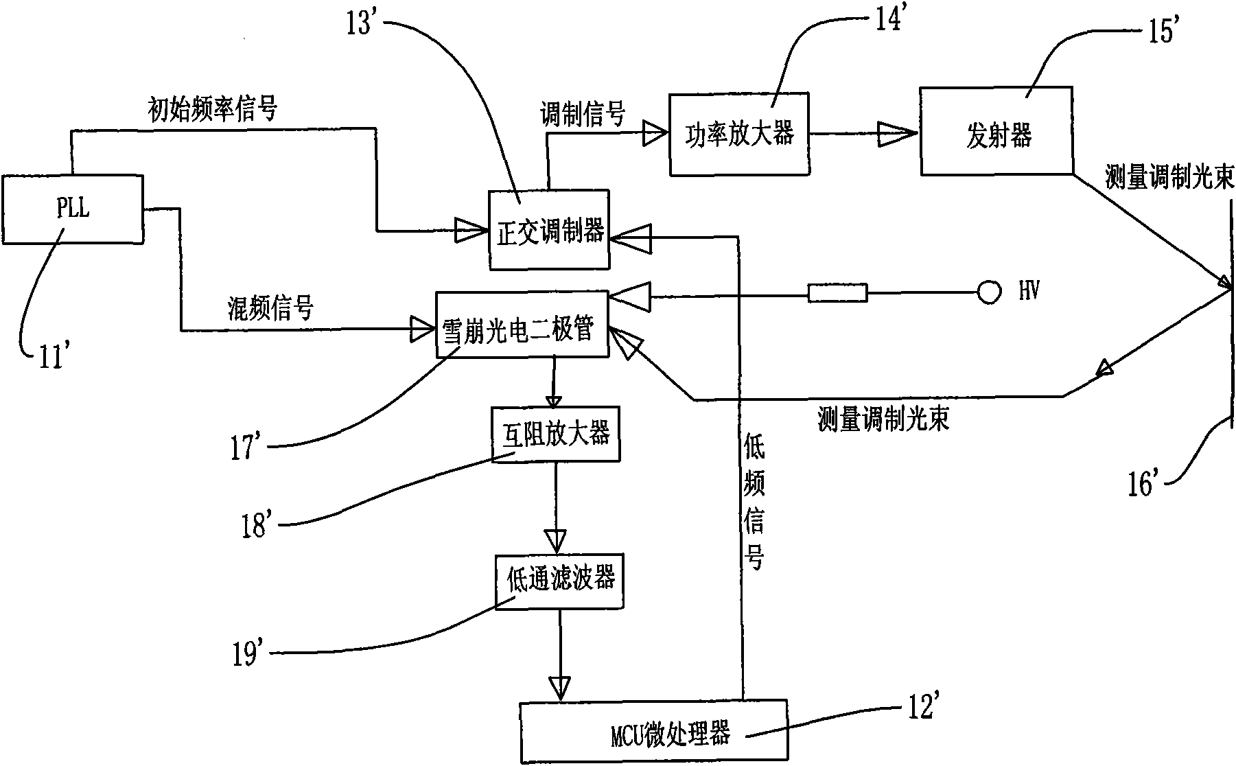
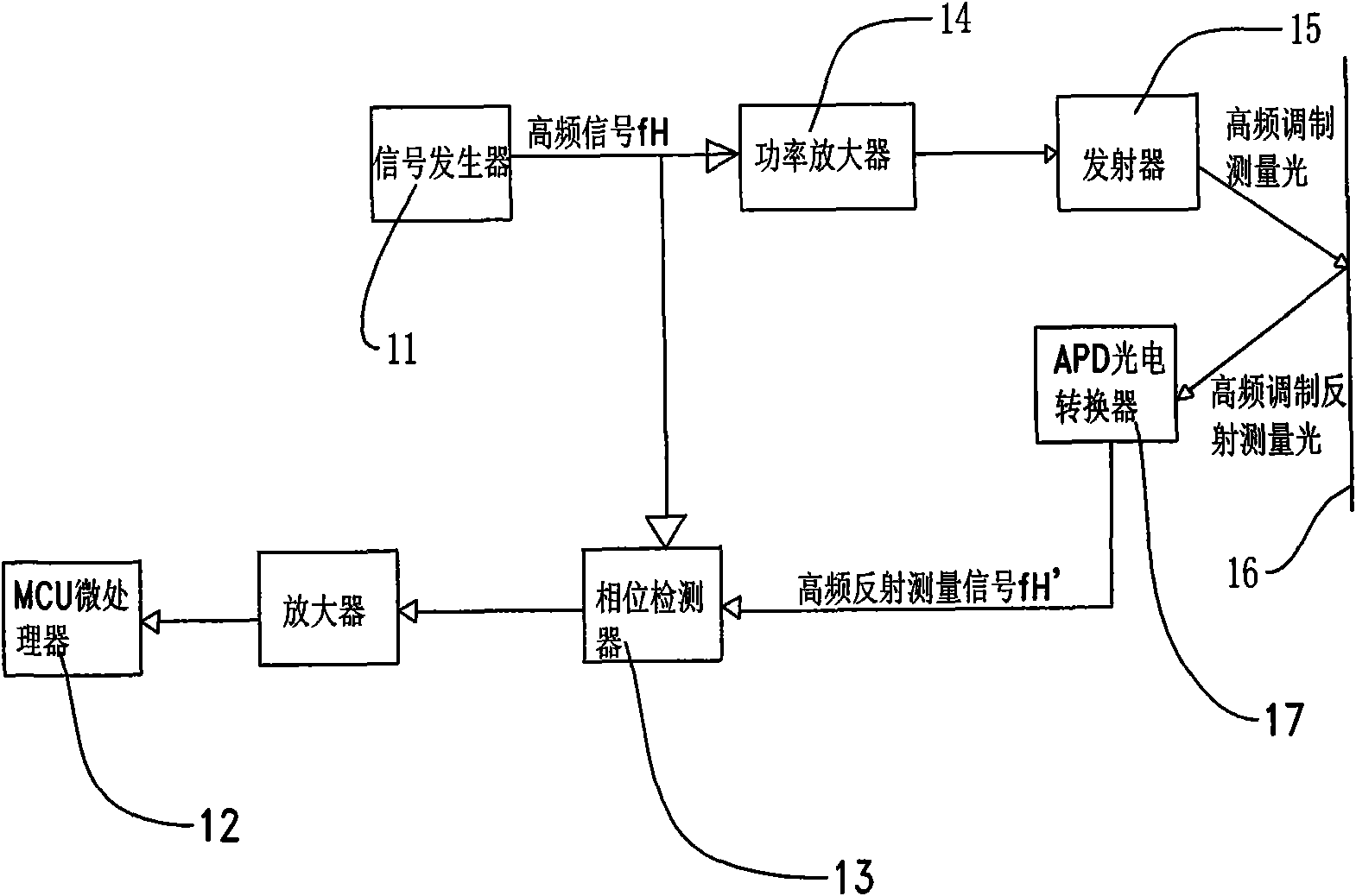
[0012] Now refer to figure 2 , the photoelectric ranging device of a preferred embodiment of the present invention mainly includes a PLL phase-locked loop circuit 11, a phase detector 13, an optical signal transmitter 15, an avalanche photodiode 17 and an MCU microprocessor 12. One of the PLL phase-locked loop circuits 11 is directly connected to the phase detector 13 through a transmission line, and the other is connected to the optical signal transmitter 15 through a power amplifier 14 . The MCU microprocessor 12 is connected with the phase detector 13 through a transmission line. The avalanche photodiode 17 is a measurement signal receiving and converting device, usually connected to a variable bias voltage through a series resistor. The phase detector 13 is a mixer capable of mixing signals.

[0013] The PLL phase-locked loop circuit 11 generates a high-frequency signal fH, and the high-frequency signal fH is input to the power amplifier 14 through the transmission line...


PUM


Abstract

The invention relates to an electro-optical distance measurement device comprising a signal generator for generating a high-frequency signal, an emitter for sending out measurement light which is subjected to the frequency modulation of the high-frequency signal to an object to be measured, an optical-electric receiving and converting device which receives reflected measurement light reflected from the object to be measured and generates a corresponding high-frequency reflection measurement signal, a phase detector which can carry out mixing processing on the high-frequency signal and a signal processing device used for determining a distance to be measured, wherein the high-frequency signal is input in the phase detector and is mixed with the high-frequency reflection measurement signal in the phase detector to generate a direct current signal, and the direct signal contains phase information for determining the distance to be measured. Since the high-frequency signal and the high-frequency reflection measurement signal which are generated and processed by the electro-optical distance measurement device have the same frequency, the beat interference on a circuit board and the electrical interference among elements in the electro-optical distance measurement device are effectively avoided.

Description

technical field [0001] The invention relates to a photoelectric distance measuring device, in particular to a phase type photoelectric distance measuring device. Background technique [0002] Photoelectric distance measuring devices, such as a laser phase distance meter, are widely used in construction, interior decoration and other fields due to their high measurement accuracy. The general principle of its measurement is: the transmitter emits a measuring modulated beam to the measured object, the photoelectric receiver receives the measured modulated beam reflected back by the measured object, and the distance is determined by the phase difference between the emitted and received measured modulated beam The distance between the meter and the measured object. [0003] figure 1 A schematic block diagram of a photoelectric ranging device based on the principle of phase ranging is shown. The PLL phase locked loop circuit 11' generates a mixed frequency signal and an origina...

Claims


Application Information

Patent Timeline
Patent Type & Authority Applications(China)
IPC IPC(8): G01S17/08G01S7/48G01S7/491
CPCG01D21/00G01D15/00G01D1/00G01S7/491G01S17/36G01C3/08
Inventor 杨德中陈武
Owner NANJING CHERVON IND
Why Eureka
Try Eureka