Method for forming end insulation of stator coil by vacuum pressure impregnation

A vacuum pressure impregnation, stator coil technology, applied in laying solid insulation, manufacturing motor generators, electrical components, etc., can solve the problems of uneven resin curing speed, unfavorable manufacturing method for rapid coil manufacturing, and large temperature difference between mold and coil, etc. To achieve the effect of uniform pressure, good rigidity and uniform wrapping

Active Publication Date: 2010-11-10
SHANGHAI ELECTRIC POWER GENERATION EQUIPMENT CO LTD
View PDF6 Cites 11 Cited by
  • Summary
  • Abstract
  • Description
  • Claims
  • Application Information

AI Technical Summary

Problems solved by technology

Each mold is heated separately. Under this heating method, the temperature difference between the mold and the coil is large, resulting in uneven curing speed of the resin on the surf

Method used


Image

  • Method for forming end insulation of stator coil by vacuum pressure impregnation
  • Method for forming end insulation of stator coil by vacuum pressure impregnation
  • Method for forming end insulation of stator coil by vacuum pressure impregnation

Examples


Embodiment 1

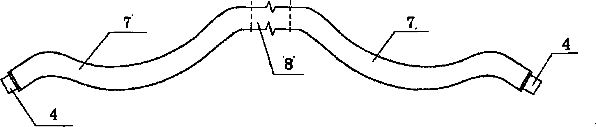
[0019] Such as figure 1 As shown, it is the front view of the stator coil. The stator coil needs to be cured after vacuum pressure impregnation treatment. Among them, the middle part 8 of the stator coil is cured by a traditional fixed mold, and the end part 7 of the stator coil is cured by the following method.

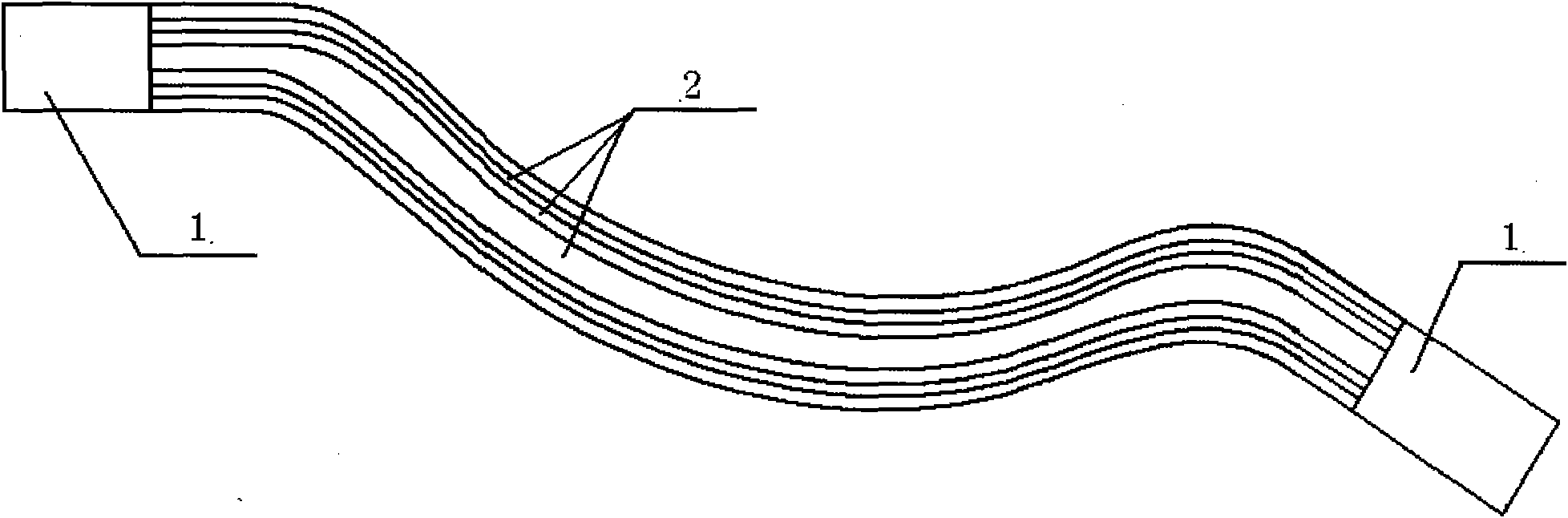
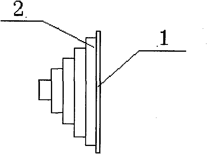
[0020] The first step is to cut the liner aluminum plate 1 according to the shape of the four sides of the stator coil end 7, the thickness of the liner aluminum plate 1 is 1 mm, and the width is between the width of the gelled coil 4 and the width of the stator coil 5 after insulation. The two ends of the backing aluminum plate 1 are 50mm longer than the ends 7 of the stator coil; cut the 2-thick unvulcanized neoprene rubber plate 2 into long strips, and the length of the unvulcanized neoprene rubber plate 2 is the same as that of the backing aluminum plate 1. The width of the first layer of unvulcanized neoprene rubber plate 2 of the liner aluminum plate 1 is 1mm s...

Embodiment 2

[0025] Such as figure 1 As shown, it is the front view of the stator coil. The stator coil needs to be cured after vacuum pressure impregnation treatment. Among them, the middle part 8 of the stator coil is cured by a traditional fixed mold, and the end part 7 of the stator coil is cured by the following method.

[0026] The first step is to cut the liner aluminum plate 1 according to the shape of the four sides of the stator coil end 7, the thickness of the liner aluminum plate 1 is 2 mm, and the width is between the width of the gelled coil 4 and the width of the stator coil 5 after insulation. Both ends of the backing aluminum plate 1 are 75mm longer than the end 7 of the stator coil; cut the 4mm thick unvulcanized neoprene rubber plate 2 into strips, the length of the unvulcanized neoprene rubber plate 2 is consistent with the liner aluminum plate 1, and it is close to the The width of the first layer of unvulcanized neoprene rubber plate 2 of the liner aluminum plate 1 is...

Embodiment 3

[0031] Such as figure 1 As shown, it is the front view of the stator coil. The stator coil needs to be cured after vacuum pressure impregnation treatment. Among them, the middle part 8 of the stator coil is cured by a traditional fixed mold, and the end part 7 of the stator coil is cured by the following method.

[0032] The first step is to cut the liner aluminum plate 1 according to the shape of the four sides of the stator coil end 7, the thickness of the liner aluminum plate 1 is 3mm, and the width is between the width of the gelled coil 4 and the width of the stator coil 5 after insulation. The two ends of the pad aluminum plate 1 are 100mm longer than the stator coil end 7; the 6mm thick unvulcanized neoprene rubber plate 2 is cut into strips, and the length of the unvulcanized neoprene rubber plate 2 is consistent with the liner aluminum plate 1. The width of the first layer of unvulcanized neoprene rubber plate 2 of the liner aluminum plate 1 is 5mm smaller than the wi...


PUM

PropertyMeasurementUnit
Thicknessaaaaaaaaaa
Widthaaaaaaaaaa
Thicknessaaaaaaaaaa

Abstract

The invention provides a method for forming end insulation of a stator coil by vacuum pressure impregnation, which is characterized by comprising the following steps: making a fiber-woven heat shrinkable wraparound sleeve; making unvulcanized hot-pressing packing strips and vulcanizing the hot-pressing packing strips; and clamping the vulcanized hot-pressing packing strips on an end surface of the stator coil which is wounded with a polytetrafluoroethylene film insulation demoulding material, winding the fiber-woven heat shrinkable wraparound sleeve on the vulcanized hot-pressing packing strips in a half-lap manner and heating the hot-pressing packing strips for solidification. In the invention, the hot-pressing packing strips adapting to the shape of the coil are manufactured and can be used repeatedly; and four hot-pressing packing strips shrink naturally to form a circular arc shape in the vulcanization process, the pressure applied by the heat shrinkable wraparound sleeve during shrinkage is uniform, the mold rigidity is high, and the coil is insusceptible to deformation under heat. The heat shrinkable wraparound sleeve with a proper shrinkage force is woven and replaces a mold in processing, the lap winding mode is changed, the pressure applied can be controlled, and the shrinkage force is uniform with the uniform lap winding.

Description

technical field [0001] The invention relates to a vacuum pressure impregnated stator coil end insulation molding method, which is used for curing the stator coil of a generator after vacuum pressure impregnation, so that the solidification becomes denser and the required insulation thickness is achieved, and the coil is prevented from being heated during the heating process. Deformation and damage belong to the technical field of motor manufacturing. Background technique [0002] In the field of energy, in the large-scale generators used in the main power grid, the insulation of the stator coil is directly related to the operational reliability, life and technical and economic indicators of the generator, and is a core component. At present, the development direction of the main insulation technology of the stator coil of large generators is mainly to thin the main insulation of the stator coil and improve the thermal conductivity, so as to improve the economic index of gene...

Claims


Application Information

Patent Timeline
IPC IPC(8): H02K15/10H02K15/12
Inventor 陈梁吴晓蕾柳成行金雯静缪莉霞韩磊
Owner SHANGHAI ELECTRIC POWER GENERATION EQUIPMENT CO LTD
Why Eureka
Try Eureka