Magnetic-electric sensing transducer

A transducer and sensing technology, applied in the field of piezoelectric devices, to achieve the effects of convenient fabrication, simple structure and fast response

Inactive Publication Date: 2010-11-10
SHANGHAI NORMAL UNIVERSITY
View PDF4 Cites 13 Cited by
  • Summary
  • Abstract
  • Description
  • Claims
  • Application Information

AI Technical Summary

Problems solved by technology

However, due to the limitation of material properties, further improving the magnetoelectric coefficient and improvi

Method used


Image

  • Magnetic-electric sensing transducer
  • Magnetic-electric sensing transducer
  • Magnetic-electric sensing transducer

Examples


Embodiment 1

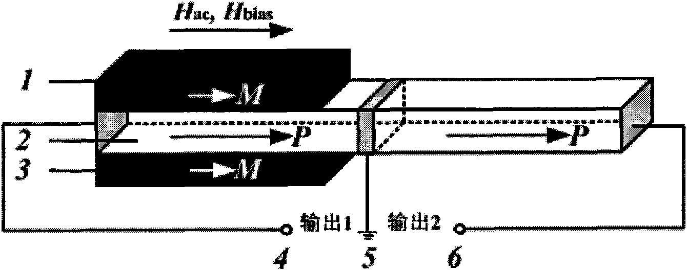
[0026] The structure of the magnetoelectric sensing transducer is as follows: figure 1 As shown, the improved Bridgman (Bridgeman) method is used to grow PMN-PT (lead magnesium niobate-lead titanate) single crystal with a composition of 0.28 direction. Electric material 2. Magnetostrictive material 1 and magnetostrictive material 3 are made of Terfenol-D (terbium dysprosium iron) alloy. The size of PMN-PT (lead magnesium niobate-lead titanate) is 16×2×2mm 3 , the size of Terfenol-D (terbium dysprosium iron) is 6×2×2mm 3 . Lead electrodes 4, 5 and 6 from 2. Non-conductive epoxy glue is used for bonding between 1, 2 and 3, so that the upper and lower layers of magnetostrictive materials and piezoelectric materials are well insulated and mechanically coupled.

Embodiment 2

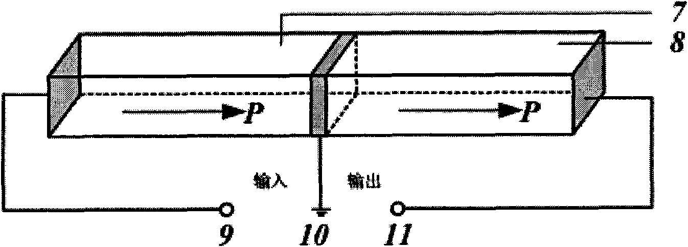
[0028] Make piezoelectric materials with amplification function, such as figure 2 As shown: the left half is the driving part 7, and the right half is the output part 8, both of which are polarized along the length direction, such as figure 2 As shown by the middle arrow, the electrode positions are shown in Figures 9, 10 and 11, the electrodes 9 and 11 are full electrodes, and the width of the electrode 10 is 1mm.

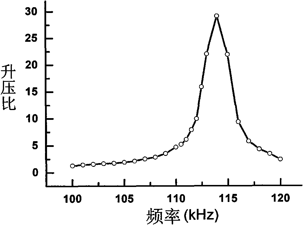
[0029] When testing the boost ratio curve of the piezoelectric material with amplification function, the signal generator is connected to the input terminal 9 and the ground terminal 10 , and the oscilloscope is connected to the output terminal 11 and the ground terminal 10 . Test results such as image 3 As shown, at about 115kHz, the step-up ratio can reach 30 times.

Embodiment 3

[0031] Test magnetoelectric coefficient:

[0032] In order to effectively transmit the strain energy of the magnetostrictive material to the piezoelectric material, Terfenol-D (terbium dysprosium iron) with a similar length is selected to stick to the piezoelectric material 2, and the size of Terfenol-D (terbium dysprosium iron) is 6 ×2×2mm 3 . After combining 1, 2 and 3 of Example 1, test its magnetoelectric coefficient, the input magnetic field amplitude is 1Oe, and the frequency range is 1-175kHz. The results show that under the best bias magnetic field of 800Oe, the input part , in the range of 1-50kHz, with stable voltage signal output, magnetoelectric coefficient α V Up to 315mV / Oe; in the resonant state, after the signal is amplified, the magnetoelectric coefficient α in the output part V Up to 7.86V / Oe.

[0033] The magnetoelectric sensing transducing device of the present invention can provide multi-terminal output. For the input end, it has a flat frequency respo...


PUM


Abstract

The invention belongs to piezoelectric devices, and discloses a high-performance magnetic-electric sensing transducer. Along with the progress of science and technology, the demands of people for detection sensitivity are becoming increasingly higher. However, due to the limitation of material properties, the demand for further improving the magnetic-electric coefficient and increasing the detection sensitivity is still a key issue which needs a solution but can not be solved easily. The magnetic-electric sensing transducer comprises a magnetostrictive material (1), a piezoelectric material (2) and a magnetostrictive material (3), the three material layers are bonded through insulating adhesives, the optimal thickness ratio of the three material layers is 1: (0.6-1): 1, and the piezoelectric material is a leadmagnesio niobate-lead titanate single-crystal material. The utility model has the advantage of multi-end output, simple structure, convenient manufacture, no need for any power supply and fast response. The input end has stable frequency response under the low frequency and is applicable to sensors, and the output end has high-voltage output in the resonant state and is suitable for high-performance transducers.

Description

technical field [0001] The invention belongs to piezoelectric devices, in particular to a high-performance magnetoelectric sensor transducer. Background technique [0002] Piezoelectric materials are crystalline materials that generate a voltage between their two ends when pressure is applied. The mutual conversion between mechanical energy and electrical energy can be realized by using the characteristics of piezoelectric materials. Piezoelectric materials are widely used in various sensors, transducers, and drivers, and have important applications in various industries and fields of modern military, science and technology, and national economy. [0003] Among them, the effective detection of weak magnetic fields is highly valued in military and civilian applications. It is widely used in many fields such as geomagnetic field detection, marine magnetic field detection, human brain magnetic field measurement, and magnetic noise measurement. It has irreplaceable advantages o...

Claims


Application Information

Patent Timeline
IPC IPC(8): H03H9/22C30B29/22H03H9/15
Inventor 王飞飞石旺舟罗豪甦
Owner SHANGHAI NORMAL UNIVERSITY
Why Eureka
Try Eureka