Double-layer crucible for growing silicon single crystals by directional solidification method

A double-layer crucible, directional solidification technology, applied in the direction of self-solidification, crystal growth, single crystal growth, etc., can solve problems such as leakage of silicon melt, and achieve the effect of improving performance, avoiding leakage and low cost

Inactive Publication Date: 2010-11-17
GREENERGY CRYSTAL TECH
View PDF6 Cites 5 Cited by
  • Summary
  • Abstract
  • Description
  • Claims
  • Application Information

AI Technical Summary

Problems solved by technology

[0004] The invention provides a double-layer crucible for growing silicon single crystal by directional solidification method, which can effectively solve the problem of placing the seed crystal, avoid the dislocation of the seed crystal during the seeding process, and completely solve the problem of the patent No. ZL 200920115886.9 The silicon melt leakage problem that is not completely solved in the Chinese utility model patent

Method used


Image

  • Double-layer crucible for growing silicon single crystals by directional solidification method
  • Double-layer crucible for growing silicon single crystals by directional solidification method
  • Double-layer crucible for growing silicon single crystals by directional solidification method

Examples


Embodiment 1

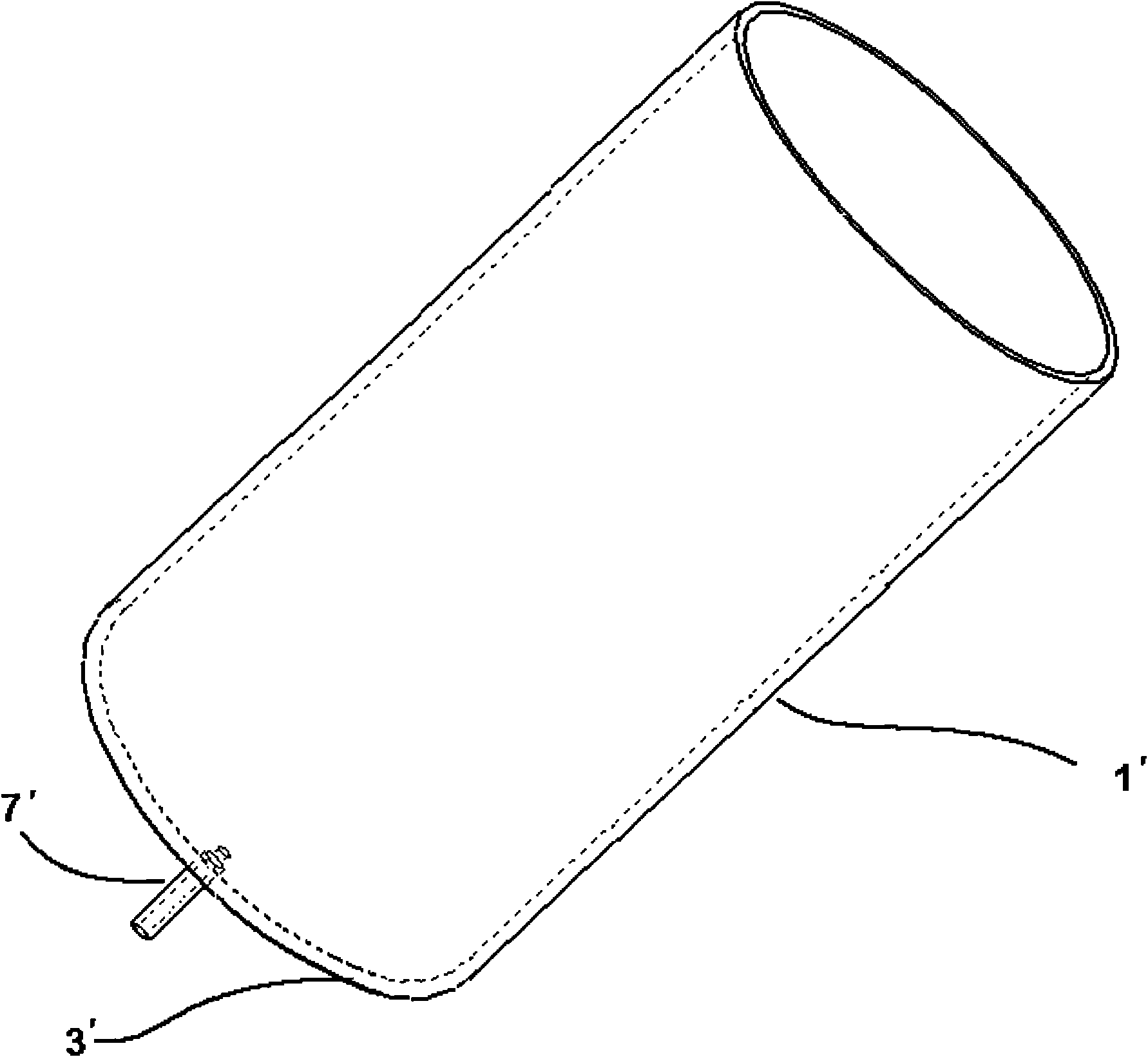
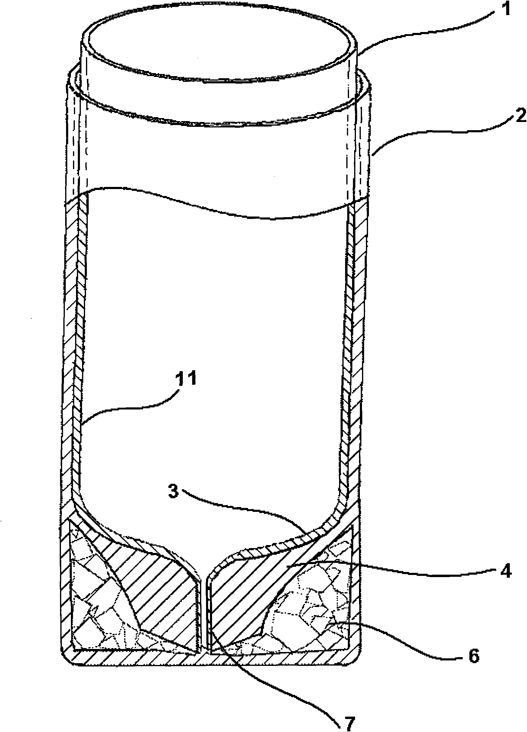
[0036] Such as figure 2 The shown double-layer crucible for growing silicon single crystal by directional solidification method includes an outer crucible and an inner crucible, and the inner crucible is nested inside the outer crucible.

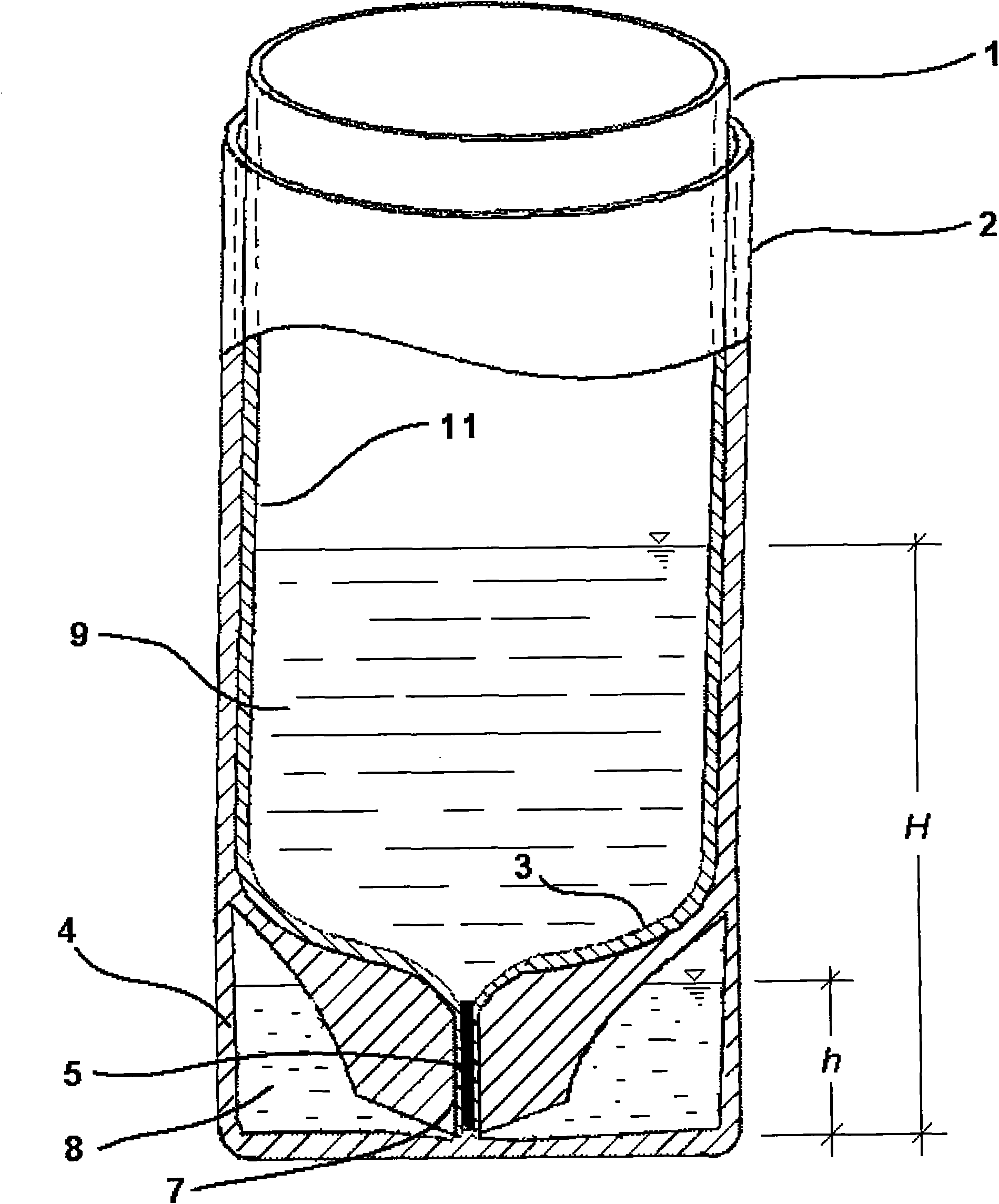
[0037] Among them, the outer crucible is made of CFC (carbon-carbon composite) material, including the outer crucible body 2 and the outer crucible bottom 4. The outer crucible bottom 4 is processed with an anti-leakage agent 6 between the inner and outer walls. The leak-proof cavity. The anti-leakage agent 6 uses high-purity tin with a purity of over 99.99%. The anti-leakage agent 6 is liquid when the temperature is higher than 232°C, has a density of about 7.3g / cm3, and does not react with silicon and is immiscible even at high temperatures (1000-2000°C).

[0038] The inner crucible is made of quartz material, including a quartz inner crucible body 1, a quartz seed crystal sleeve 7, and a quartz inner crucible bottom 3, where the inner crucib...

Embodiment 2

[0045] In the same way as in Example 1, the difference is that BaF with a mass ratio of 1:1 2 And BaCl 2 The mixture (in powder form) is used as an anti-leakage agent 6. BaF 2 The melting point is 1360℃ and the density is 4.89g / cm 3 . BaCl 2 The melting point is 962℃ and the density is 3.1g / cm 3 . Therefore, BaF with a mass ratio of 1:1 is used 2 And BaCl 2 The density of the mixture is greater than that of silicon (2.33g / cm3), and the melting point is lower than that of silicon (1415°C). At the same time, BaF 2 And BaCl 2 The melt does not react with or dissolve in silicon melt between 1400°C and 2000°C.

Embodiment 3

[0047] In the same manner as in Example 1, the difference is that the cross-sectional areas of the inner crucible body 1 and the outer crucible body 2 are square.


PUM

PropertyMeasurementUnit
heightaaaaaaaaaa
heightaaaaaaaaaa
melting pointaaaaaaaaaa

Abstract

The invention discloses a double-layer crucible for growing silicon single crystals by a directional solidification method, which comprises an outer crucible and an inner crucible nested into the outer crucible, wherein the inner crucible comprises an inner crucible main body and an inner crucible bottom; the outer crucible comprises an outer crucible main body and an outer crucible bottom; the inner crucible bottom is provided with a seed crystal sleeve for placing seed crystals; the outer crucible bottom is provided with an anti-leakage cavity; an anti-leakage agent is placed in the anti-leakage cavity; and the internal cavity of the inner crucible main body is communicated with the anti-leakage cavity through the internal cavity of the seed crystal sleeve. The anti-leakage agent is not reacted with silicon and is immiscible with the silicon, the density of the anti-leakage agent is more than 2.4g/cm<3>, and the melting temperature of the anti-leakage agent is less than 1,410 DEG C. The double-layer crucible can effectively solve the seed crystal placing problem, realizes silicon single crystal growth by the directional solidification method, meanwhile can furthest prevent molten silicon from leaking from the seed crystal sleeve, has low cost and a simple structure, and is easy to process.

Description

Technical field [0001] The present invention relates to a device for manufacturing silicon single crystals, in particular to a container for placing silicon raw materials in a thermal field for directional solidification to grow silicon single crystals, that is, a crucible for directional solidification to grow silicon single crystals. Background technique [0002] Silicon single crystal and silicon polycrystalline ingots are the most commonly used materials for crystalline silicon solar cells. Generally, solar cells made of silicon single crystal materials have higher photoelectric conversion efficiency than solar cells made of silicon polycrystalline materials. At present, the most commonly used manufacturing methods for silicon single crystals are the Czochralski method and the Floating Zone method; the manufacturing methods for silicon polycrystals usually use the directional solidification method (ie, the casting method). The directional solidification method is to place th...

Claims


Application Information

Patent Timeline
Patent Type & Authority Applications(China)
IPC IPC(8): C30B11/00
Inventor 李乔马远
Owner GREENERGY CRYSTAL TECH
Why Eureka
Try Eureka