Frequency scanning antenna array capable of realizing wide-angle scanning in limited bandwidth
A frequency scanning antenna, limited bandwidth technology, applied in the field of frequency scanning antenna array, can solve the problems of increased loss, complex structure, huge energy, etc., to achieve the effects of light weight, convenient implementation and simple structure
- Summary
- Abstract
- Description
- Claims
- Application Information
AI Technical Summary
Problems solved by technology
Method used
Image
Examples
Embodiment 1
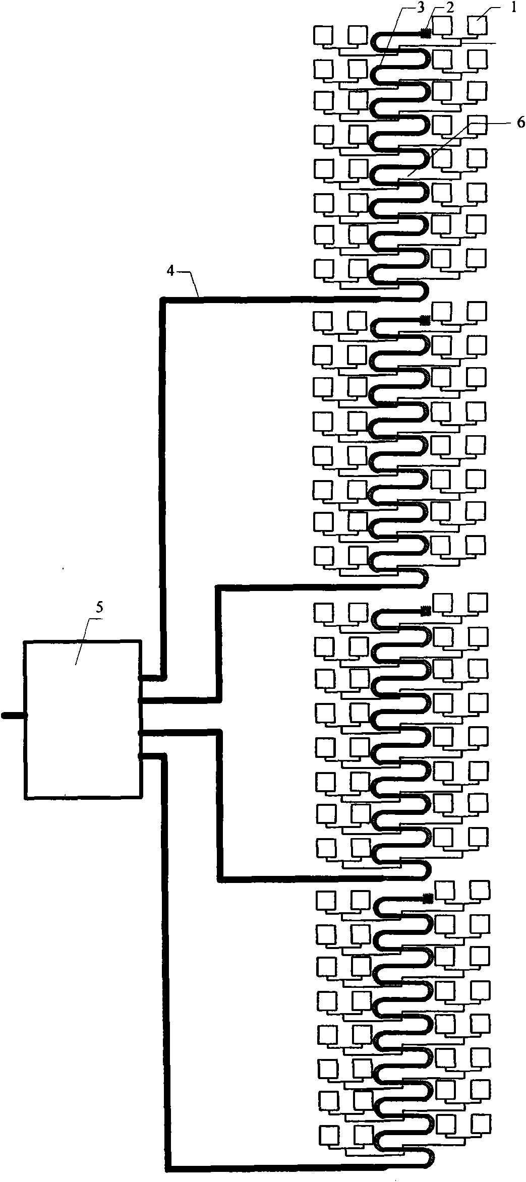
[0022] The frequency range used was 8.5-10.5 GHz, the scanning angle was ±45°, the dielectric constant of the used dielectric plate was 2.2, the thickness was 1 mm, and the loss angle was 0.0009.
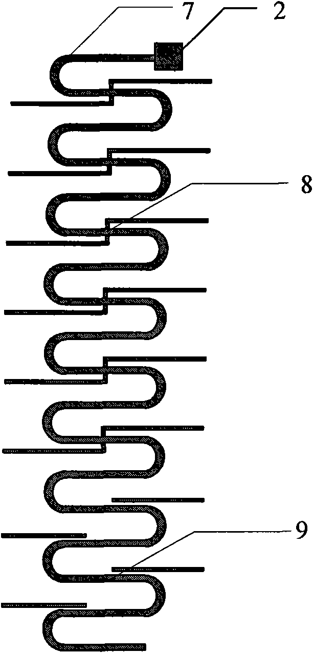
[0023] The antenna array structure is composed of 128 microstrip antenna units, and the array is 32×2. Every 8 × 2 cells form a sub-array, and there are four sub-arrays in total. The row spacing and column spacing of adjacent microstrip antenna units in the array are both equal to 0.52 spatial wavelengths. According to the bandwidth and scanning angle, the length of the slow wave line of each microstrip unit phase cabinet is four wavelengths. According to the measured results, the loss per wavelength of the microstrip line on this medium is 0.12dB. If it is such a loss value, the loss value of the 32-element array on the slow wave line is 14.88dB, which is very surprising and unacceptable in practical design. At the same frequency, the measured loss of the coaxial line is 0.02dB ...
Embodiment 2
[0026] The frequency range used was 8.5-10.5 GHz, the scanning angle was ±45°, the dielectric constant of the used dielectric plate was 2.2, the thickness was 1 mm, and the loss angle was 0.0009.
[0027] The antenna array structure described is composed of 256 microstrip antenna elements, and the array is arranged in a 64×2 arrangement. Every 8 × 2 cells form a sub-array, with a total of 8 arrays. The row spacing and column spacing of adjacent microstrip antenna units in the array are both equal to 0.52 spatial wavelengths. According to the bandwidth and scanning angle, the length of the slow wave line of each microstrip unit phase cabinet is four wavelengths. According to the measured results, the loss per wavelength of the microstrip line on this medium is 0.12dB. If it is such a loss value, the loss value of the 64-element array on the slow wave line is 30.24dB, which is very surprising and unacceptable in practical design. At the same frequency, the measured loss of th...
Embodiment 3
[0029] The frequency range used was 8.5-10.5 GHz, the scanning angle was ±45°, the dielectric constant of the used dielectric plate was 2.2, the thickness was 1 mm, and the loss angle was 0.0009.
[0030] The antenna array structure described is composed of 512 microstrip antenna elements, and the array is 128×2. Every 8 × 2 cells form a sub-array, with a total of 16 arrays. The row spacing and column spacing of adjacent microstrip antenna units in the array are both equal to 0.52 spatial wavelengths. According to the bandwidth and scanning angle, the length of the slow wave line of each microstrip unit phase cabinet is four wavelengths. According to the measured results, the loss per wavelength of the microstrip line on this medium is 0.12dB. If it is such a loss value, the loss value of the 128-element array on the slow wave line is 60.96dB, which is very surprising and unacceptable in practical design. At the same frequency, the measured loss of the coaxial line is 0.02d...
PUM
| Property | Measurement | Unit |
|---|---|---|
| Thickness | aaaaa | aaaaa |
Abstract
Description
Claims
Application Information
 - R&D
- Intellectual Property
- Life Sciences
- Materials
- Tech Scout
- Unparalleled Data Quality
- Higher Quality Content
- 60% Fewer Hallucinations
Browse by: Latest US Patents, China's latest patents, Technical Efficacy Thesaurus, Application Domain, Technology Topic, Popular Technical Reports.
© 2025 PatSnap. All rights reserved.Legal|Privacy policy|Modern Slavery Act Transparency Statement|Sitemap|About US| Contact US: help@patsnap.com


