
Method and die for molding skins front edges of rotary wings of aircraft by stretching and compressing

A leading edge skin and aircraft technology, applied in forming tools, manufacturing tools, metal processing equipment, etc., can solve the problems of low straightness and poor forming surface, and improve forming accuracy, straightness and consistency Good, reduce the effect of elastic rebound

Inactive Publication Date: 2010-11-24
HARBIN
View PDF4 Cites 12 Cited by
  • Summary
  • Abstract
  • Description
  • Claims
  • Application Information

AI Technical Summary

Problems solved by technology

[0004] The present invention is aimed at the shortcoming existing in the above-mentioned prior art and designs and provides a kind of aircraft machine, rotor leading edge skin drawing and pressing forming method and forming mold, and its purpose is to solve existing aircraft machine, rotor leading edge skin During the forming process, the forming surface is not good and the straightness along the length of the part is not high.

Method used


Image

  • Method and die for molding skins front edges of rotary wings of aircraft by stretching and compressing
  • Method and die for molding skins front edges of rotary wings of aircraft by stretching and compressing
  • Method and die for molding skins front edges of rotary wings of aircraft by stretching and compressing

Examples


Embodiment Construction

[0024] The technical scheme of the present invention will be described in further detail below in conjunction with accompanying drawing and embodiment:

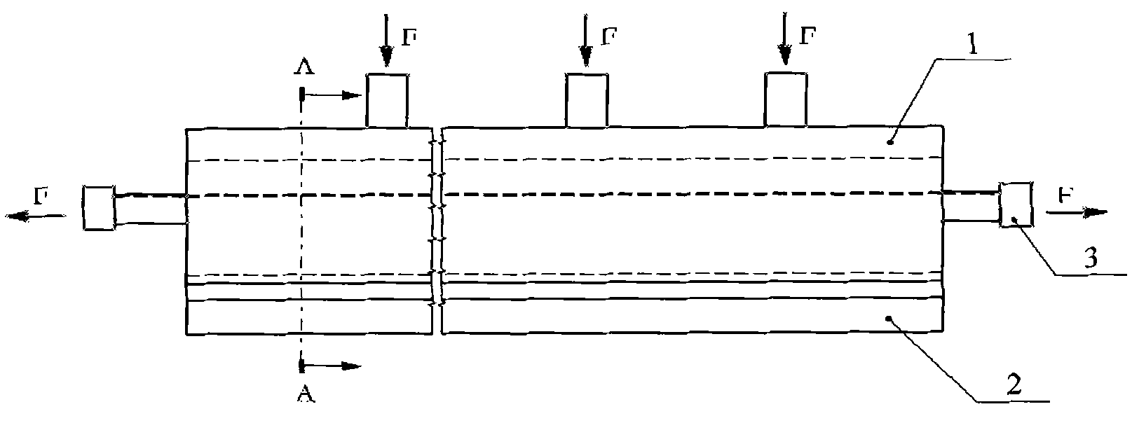
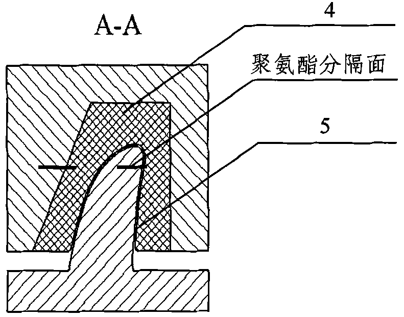
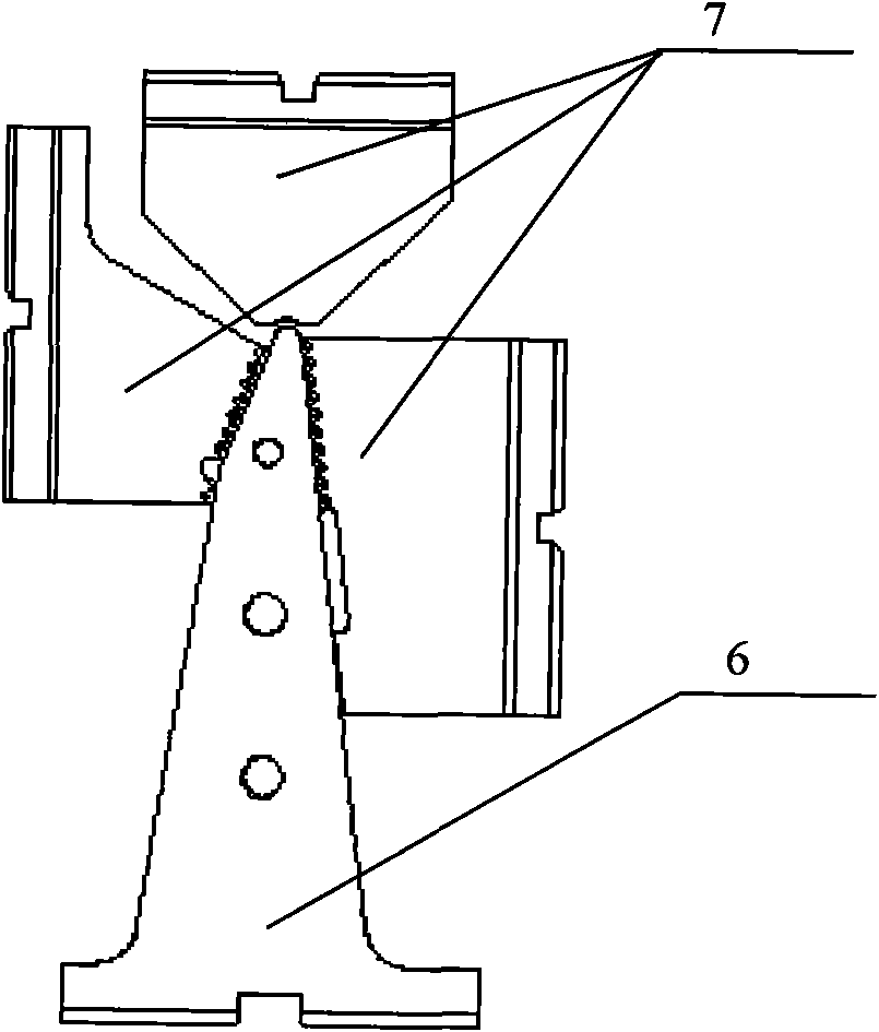
[0025] See attached Figure 1~3 As shown, the mold is composed of a forming die and a chuck. The core part is a forming die. The forming die is composed of a lower die 2 and an upper die 1. The lower die 2 is a rigid punch. The convex model surface and the inner surface of the part Consistent, the material is No. 45 steel, quenched to HRC33-38, the upper mold 1 is a die structure, which is composed of a rigid frame and a polyurethane lining, the rigid frame is a Q235 steel plate welded structure, and the polyurethane lining contains two Two types of hardness, with the polyurethane separating surface as the boundary, the Shore hardness of the concave top polyurethane layer 4 is 90, the Shore hardness of the side polyurethane layers 5 on both sides is 70, and the components and volume ratios of the top polyurethane layer 4 are:...


PUM


Abstract

The invention relates to a method and a die for molding skins of the front edges of rotary wings of an aircraft by stretching and compressing. The technical scheme abandons the traditional bake compressing and molding process and provides a comprehensive molding method combining the stretching along the length direction of a part and the bending along the radial direction to guarantee that all molding areas along the length direction of the part are in a tension stress state in the molding process of the part. In addition, in the part molding process, a rigid convex die and an elastic concave die are matched, and in the part bending process, the elastic concave die can generate a coating effect on the part in the tangential direction so as to be beneficial to molding the part. Under the alternate actions of the molding process and the bending process, the elastic resilience of the molded part is reduced, and the molding precision and the straightness of the part are improved.

Description

technical field [0001] The invention relates to an aircraft machine, a method for stretching and pressing the leading edge skin of a rotor and a forming die, and belongs to the technical field of material forming and processing. Background technique [0002] Aircraft machine and rotor leading edge skin forming technology are the key manufacturing technologies of helicopters. The common practice now is to use brake pressure forming to manufacture machine and rotor leading edge skins. The method adopts gate pressure rods of different diameters to form gates one by one in order of diameter from large to small. The processing sequence is to form both sides of the skin first, and then form the top of the skin. During the forming process, use a sample to check, and cut the allowance after forming. The deviation between the parts manufactured by this method and the theoretical appearance is about 1.5 millimeters, the straightness tolerance of the parts is 2 to 3 millimeters, and ...

Claims


Application Information

Patent Timeline
IPC IPC(8): B21D35/00B21D37/10
Inventor 刘军基侯本来曹晋
Owner HARBIN
Learn More