Vertical single-column cantilever type large-aperture honing machine

A cantilever-type, single-column technology, applied in honing machine tools, metal processing equipment, manufacturing tools, etc., can solve problems such as low requirements for alignment and alignment, complex structure of ball-joint connecting rods, and reduced strength of connecting rods, etc., to achieve Eliminate jamming, simplify the process of workpiece alignment, and improve production efficiency

Inactive Publication Date: 2010-11-24
YANGZHOU METALLURGICAL MACHINERY
View PDF7 Cites 4 Cited by
  • Summary
  • Abstract
  • Description
  • Claims
  • Application Information

AI Technical Summary

Problems solved by technology

[0005] At the same time, we also found that the above-mentioned honing head connecting rods for large holes and deep long holes generally use ball-head floating connecting rods. This structure does not require high alignment and centering of the workpiece, and can easily realize large and medium-sized holes. Long-hole honing of complex and irregular heavy workpieces, but the structure of the ball-joint connecting rod itself is complex, and a through hole needs to be left in the shaft center to pass through the honing head oil stone seat expansion-shrinking ejector rod, which reduces the strength of the connecting rod , so that the maintenance and maintenance of the equipment in the process of manufacturing, assembly and later use is relatively large, and the cost is relatively high

Method used


Image

  • Vertical single-column cantilever type large-aperture honing machine
  • Vertical single-column cantilever type large-aperture honing machine
  • Vertical single-column cantilever type large-aperture honing machine

Examples


Embodiment Construction

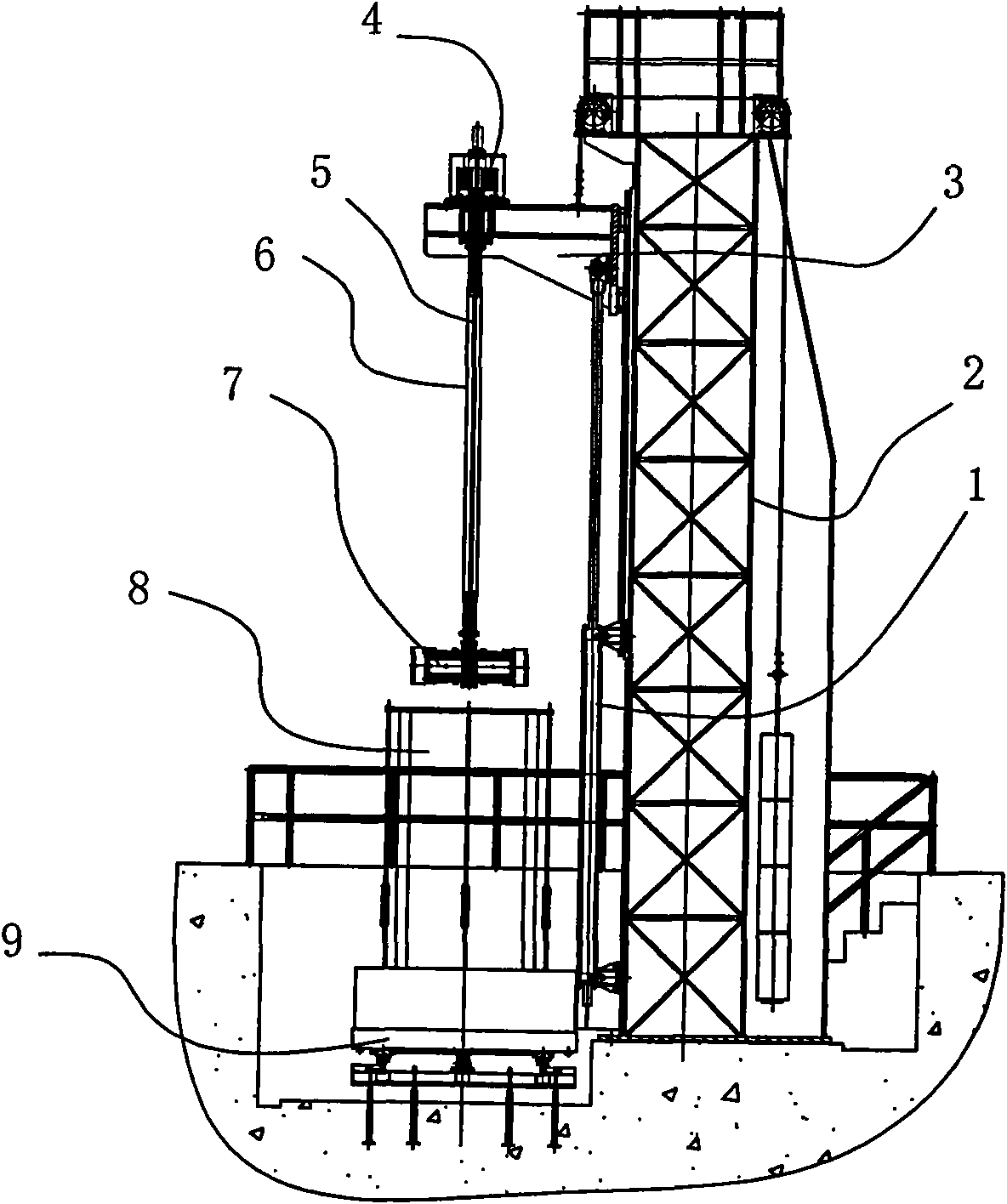
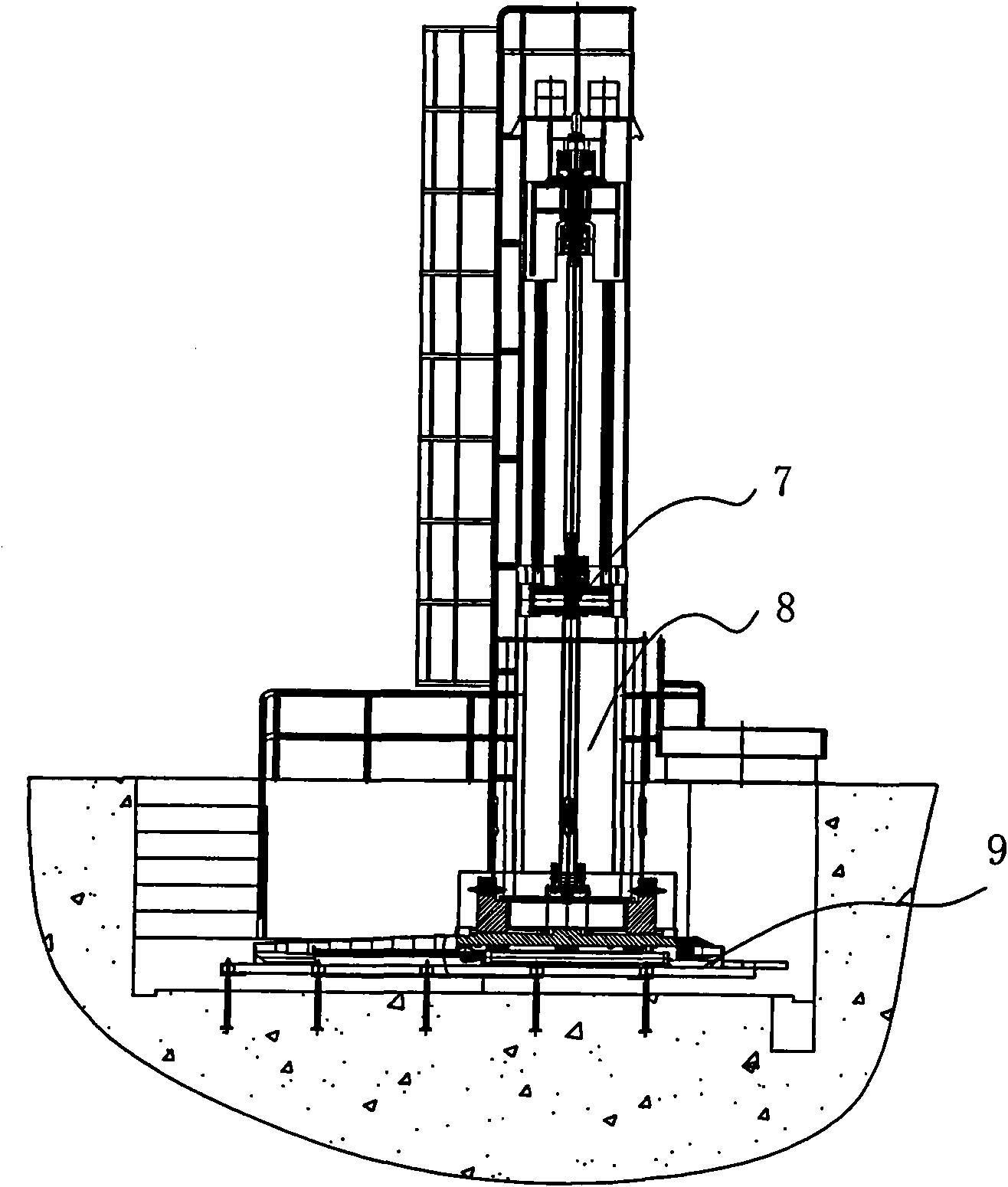
[0022] The invention as Figure 1-5 As shown, including frame 2, workbench 9, honing head device and honing head device lifting drive mechanism;

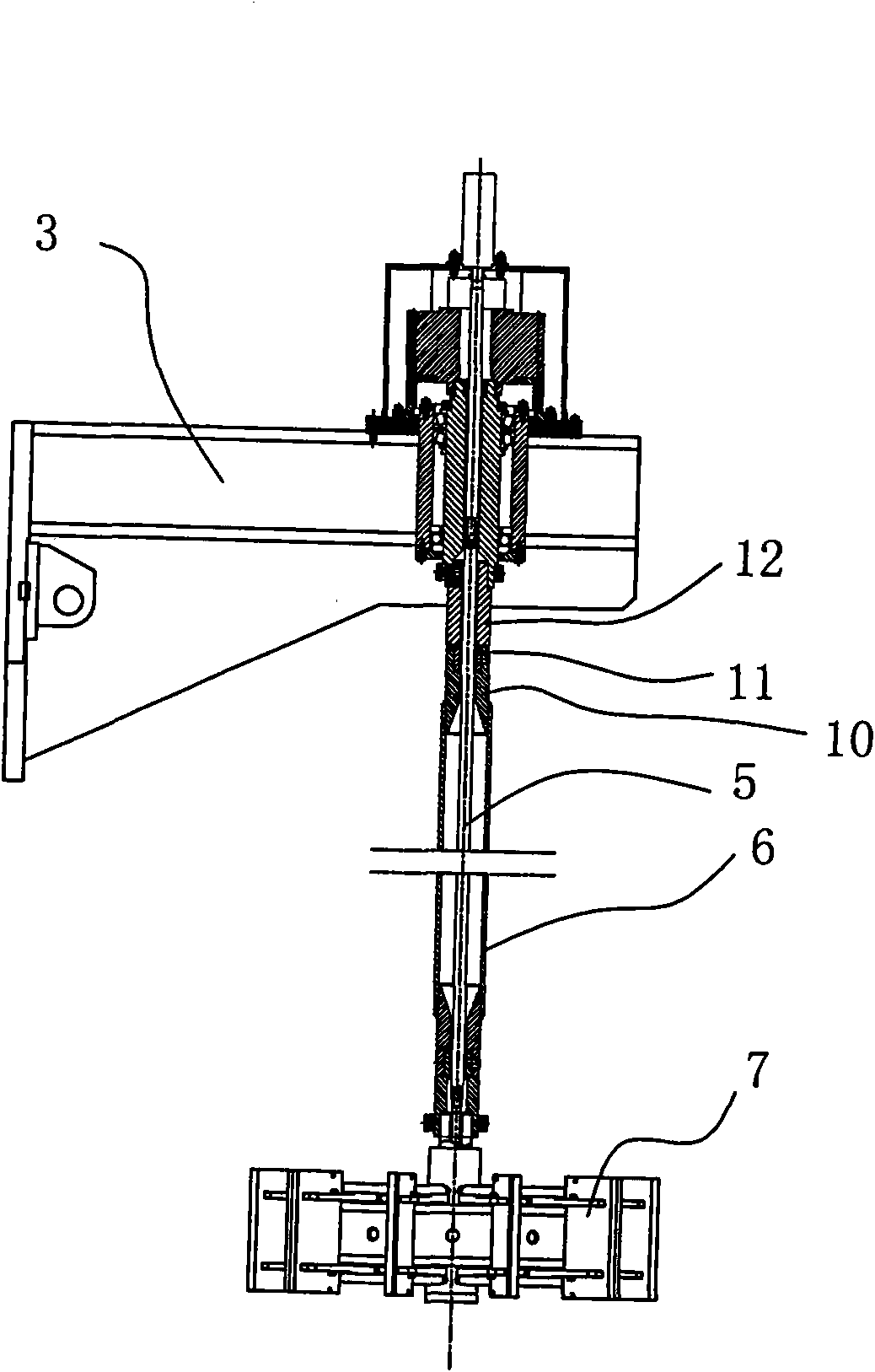
[0023] The lifting drive mechanism of the honing head device includes a cantilever-type lifting seat 3 and a lifting cylinder 1; the lifting cylinder 1 is fixedly connected to the side of the frame 2 to drive the lifting seat 3 to move up and down; the honing head device Connected to the lifting seat 3, the honing head device is perpendicular to the horizontal plane;

[0024] Described workbench 9 comprises the base and the platen 14 of horizontal setting, and platen 14 is connected with base by linear guide rail 15; Described platen 14 is provided with fixture 13; The longitudinal axis level of described workbench 9, and with all The axes of the honing head device are in the same vertical plane;

[0025] The honing head device is an expansion-contracting honing head device comprising a drive hydraulic motor 4, a hollow shaft 6, a...


PUM


Abstract

The invention relates to a vertical single-column cantilever type large-aperture honing machine which relates to a hole-honing special machine. In the honing machine, the lifting drive mechanism of a honing head device comprises a cantilever type pedestal and a lift cylinder, wherein the lift cylinder drives the pedestal to move up and down; the honing head device is a collapsible honing head device containing a drive hydraulic motor, a hollow shaft, a mandrel, a wedge cylinder, a honing head disk with a center hole, a push rod and an abrasive stick; the abrasive stick is vertically and movably connected on the outside cylinder surface of the honing head disk through the push rod; the wedge cylinder is arranged in the center hole of the honing head disk; the lower end of the hollow shaft is fixedly connected with the top surface of the honing head disk to drive the honing head disk to rotate; the mandrel is arranged in the hollow shaft, the lower end of the mandrel is connected with the wedge cylinder to drive the wedge cylinder to move up and down; and the push rod is movably connected in the honing head disk along the radial direction of the honing head disk, the inner end of the push rod sticks to the wedge face of the wedge cylinder, and the outer end is connected with the abrasive stick. By using the honing machine of the invention, the use reliability of equipment is greatly improved, the service life of equipment is prolonged, and the maintenance cost of equipment is reduced.

Description

technical field [0001] The invention relates to a special machine tool for honing the inner hole of a large-diameter workpiece, in particular to a large-diameter honing machine tool with a vertical single-frame cantilever structure, which can be widely used in rolling equipment in the metallurgical industry for roll sleeves and similar workpieces. The technical field of honing processing. Background technique [0002] Honing is a low-speed grinding method, which is often used for smoothing and finishing the inner hole surface. [0003] The inner diameter of commonly used roll sleeves in China is mostly between φ500~φ1200mm, and the hole length range is ≤2400mm. It is difficult for the existing honing machine for honing the inner diameter of the above range to cover the entire size range, or there are too many machine tool accessories, which makes economic benefits Not high, and the maintenance of equipment is large. Such as honing machines with horizontal frame structure a...

Claims


Application Information

Patent Timeline
Patent Type & Authority Applications(China)
IPC IPC(8): B24B33/02
Inventor 李波王晨李相娟安娜庞康花迪春缪昌华
Owner YANGZHOU METALLURGICAL MACHINERY
Why Eureka
Try Eureka