Cathode blanked non-inert anode super pseudo-capacitor
A pseudocapacitor and anode technology, applied in the field of capacitors, can solve the problem of high cost, achieve sufficient raw materials, avoid power loss, and quickly charge the effect
- Summary
- Abstract
- Description
- Claims
- Application Information
AI Technical Summary
Problems solved by technology
Method used
Image

Examples
Embodiment Construction
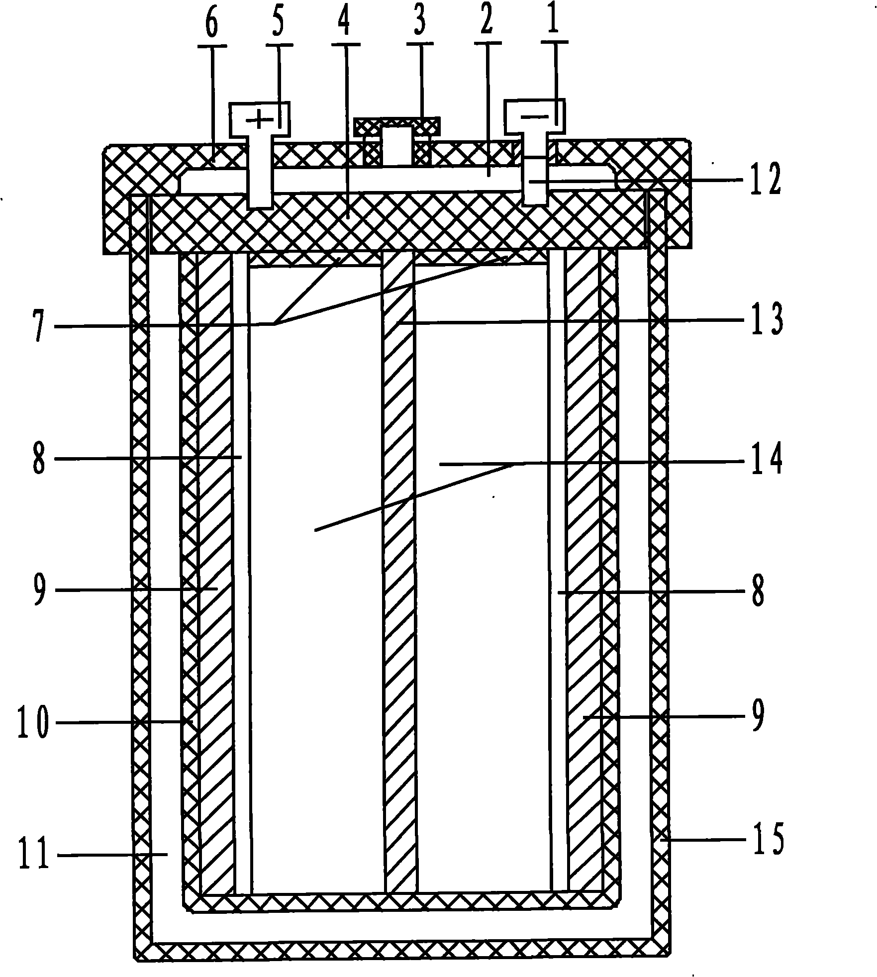
[0020] exist figure 1 Among them, the main body 10 is located in the shell 15, the anode current collector 9 is located in the main body 10, the inside of the anode current collector 9 is covered with an amorphous silicon layer as the anode working surface 8, and the electrolyte is filled in the anode current collector 9 and the cathode current collector in the main body 10. Between the fluids 13, the electrolyte is supersaturated copper sulfate ammonium electrolyte or copper cyanide electrolyte. The cathode current collector 13 is located in the center of the body 10, the wire crimping plate 4 is embedded in the upper end of the body 10, the upper end of the casing 15 is packaged with a head 6, the air-repelling heat dissipation plug 3 is arranged on the head 6, and the anode pile 5 on the head 6 The cathode pile 1 is connected to the anode current collector 9 and the cathode current collector 13 respectively through the pressure plate 4 .
[0021] The body 20 and the pressu...
PUM
| Property | Measurement | Unit |
|---|---|---|
| thickness | aaaaa | aaaaa |
| diameter | aaaaa | aaaaa |
Abstract
Description
Claims
Application Information
 - R&D
- Intellectual Property
- Life Sciences
- Materials
- Tech Scout
- Unparalleled Data Quality
- Higher Quality Content
- 60% Fewer Hallucinations
Browse by: Latest US Patents, China's latest patents, Technical Efficacy Thesaurus, Application Domain, Technology Topic, Popular Technical Reports.
© 2025 PatSnap. All rights reserved.Legal|Privacy policy|Modern Slavery Act Transparency Statement|Sitemap|About US| Contact US: help@patsnap.com