Electroluminescent display panel and pixel structure thereof

A technology for display panels and electroluminescence, which is applied in the direction of circuits, electrical components, and electric solid devices, and can solve the problems of increased overall voltage drop, different luminous efficiencies, and uneven display brightness of electroluminescent display panels 10, so as to reduce Overall pressure drop, improving the effect of uneven display brightness

Inactive Publication Date: 2010-11-24
AU OPTRONICS CORP
View PDF6 Cites 14 Cited by
  • Summary
  • Abstract
  • Description
  • Claims
  • Application Information

AI Technical Summary

Problems solved by technology

However, due to the different luminescent properties of the luminescent materials, for example, the luminous efficiencies of blue electroluminescent elements, green electroluminescent elements and red electroluminescent elements are not the same (generally speaking, the luminous efficiency of blue electroluminescent elements is generally low. (Green electroluminescence element and red electroluminescence element), plus the human eye's acceptance of different colors of light is also different, so the equal-width power line design increases the overall voltage drop of the known electroluminescence display panel 10 , and the problem of uneven display brightness of the electroluminescent display panel 10 is more serious

Method used


Image

  • Electroluminescent display panel and pixel structure thereof
  • Electroluminescent display panel and pixel structure thereof
  • Electroluminescent display panel and pixel structure thereof

Examples


Embodiment Construction

[0034] In order to enable those of ordinary skill in the technical field of the present invention to further understand the present invention, the preferred embodiments of the present invention are enumerated below, together with the accompanying drawings, to describe in detail the composition of the present invention and the desired effects .

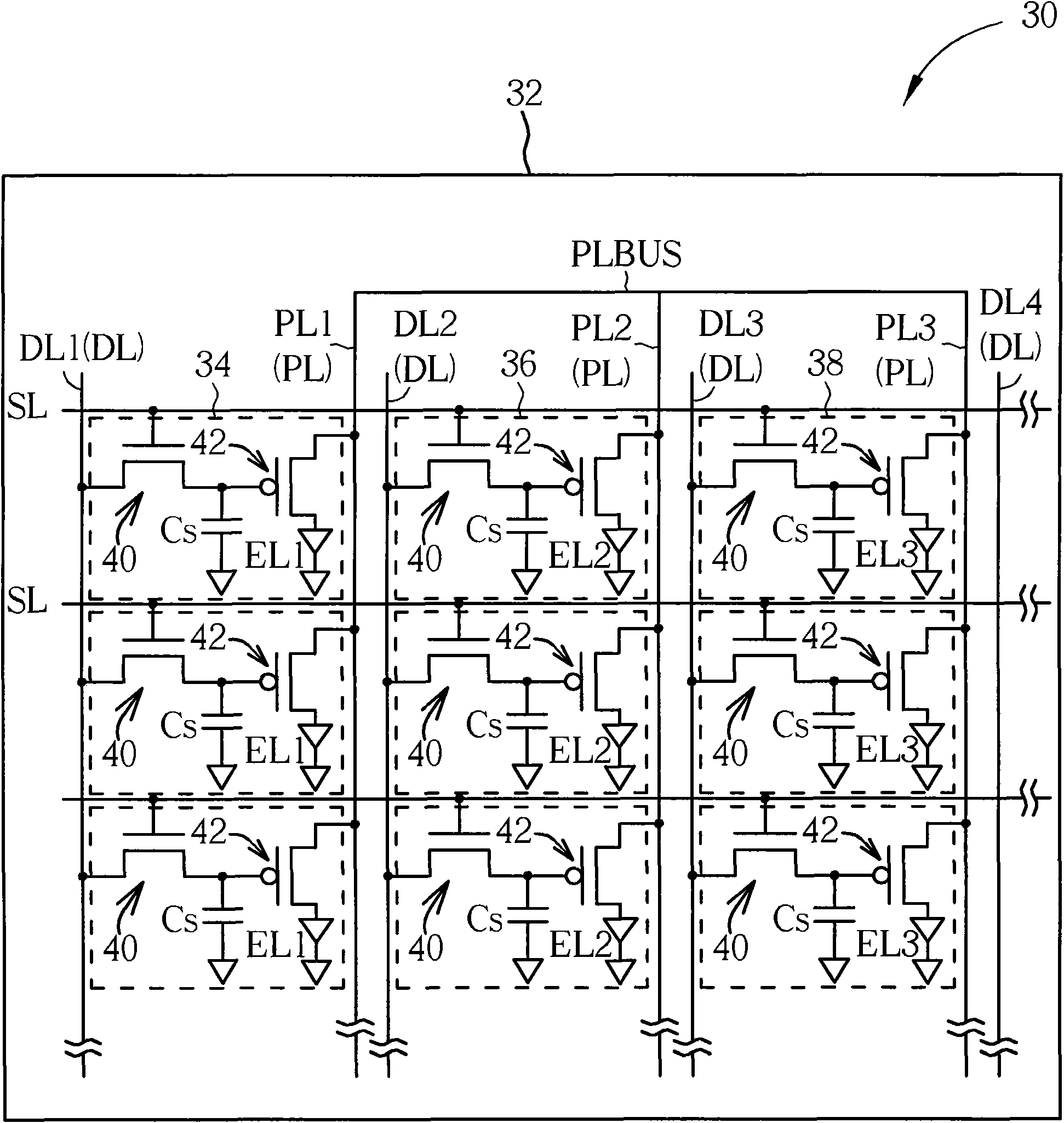
[0035] Please refer to figure 2 . figure 2 A schematic diagram of an electroluminescence display panel according to a preferred embodiment of the present invention is shown. In the present invention, the electroluminescent display panel may be an organic light emitting diode (OLED) display panel, a polymer light emitting diode (PLED) display panel or other various types of electroluminescent display panels. Such as figure 2 As shown, the electroluminescent display panel 30 of this embodiment includes a substrate 32 , a plurality of scan lines SL and a plurality of data lines DL. The scan lines SL are substantially parallel to ea...


PUM


Abstract

The invention discloses an electroluminescent display panel, which comprises a blue electroluminescent element, a red electroluminescent element, a green electroluminescent element, a first power line electrically connected with the blue electroluminescent element, a second power line electrically connected with the red electroluminescent element, and a third power line electrically connected with the green electroluminescent element. The first power line has a first wire width, the second power line has a second wire width, the third power line has a third wire width, wherein the first wire width is greater than the second wire width, and the first wire width is greater than the third wire width. The invention also discloses a pixel structure of the electroluminescent display panel.

Description

technical field [0001] The invention relates to an electroluminescent display panel and its pixel structure, in particular to an electroluminescent display panel with unequal line width designed power lines and its pixel structure. Background technique [0002] Electroluminescent display, due to its light and thin size, high resolution, high contrast ratio, power saving and active light emission, has surpassed liquid crystal display and has become the mainstream product of the next generation flat and thin display. [0003] Please refer to figure 1 . figure 1 A schematic circuit structure diagram of a known pixel structure of an electroluminescent display panel is shown. Such as figure 1 As shown, the conventional electroluminescence display panel 10 includes a plurality of pixel structures 12 , and each pixel structure 12 includes a pixel switch element 14 , a driving switch element 16 , a storage capacitor Cs and an electroluminescence element EL. The gate, source and ...

Claims


Application Information

Patent Timeline
Patent Type & Authority Applications(China)
IPC IPC(8): H01L27/32H01L23/50G09F9/33
Inventor 聂建名
Owner AU OPTRONICS CORP
Why Eureka
Try Eureka