Current feed three-inductor boost converter of high frequency transformer connected in delta/Y shape

A technology of high-frequency transformers and three-phase transformers, which is applied in the direction of converting DC power input to DC power output, output power conversion devices, instruments, etc., and can solve the problem of large leakage inductance of high-turn ratio transformers, switching losses, and large leakage inductance of transformers etc. to achieve the effects of reducing input current ripple, balancing heat distribution, and improving reliability

Inactive Publication Date: 2012-12-05
SOUTH CHINA UNIV OF TECH
View PDF0 Cites 0 Cited by
  • Summary
  • Abstract
  • Description
  • Claims
  • Application Information

AI Technical Summary

Problems solved by technology

In recent years, some high-gain DC-DC conversion circuits have been studied successively. There are two main types: one is the push-pull forward converter, which is essentially an isolated push-pull converter. This converter is a basic step-down converter. The deformation of the full-bridge converter still needs to rely on the turn ratio of the high-frequency transformer to achieve high-gain voltage output. Due to the large leakage inductance of the transformer, there are also switching losses and reverse recovery losses similar to the full-bridge converter; another The first class is a two-stage power converter. For example, the front stage is a basic step-up converter, and the rear stage is an open-loop bridge converter. In this case, the latter stage converter is equivalent to an electronic transformer. The two-stage power converter It is possible to achieve a high-gain output voltage, but there are five power switch tubes and five output rectifier diodes in the entire conversion topology, so in the case of low-voltage input, there are still switching losses caused by leakage inductance and reverse recovery losses
Although these two types of high-gain isolated DC-DC converters achieve high-gain voltage output through a very high transformer turn ratio, the external power circuit is complicated, and the high-turn ratio transformer has a large leakage inductance, so the power cannot be reduced. The voltage stress of the switch tube and the output rectifier diode limits the further improvement of the working efficiency of the converter

Method used


Image

  • Current feed three-inductor boost converter of high frequency transformer connected in delta/Y shape
  • Current feed three-inductor boost converter of high frequency transformer connected in delta/Y shape

Examples


Embodiment Construction

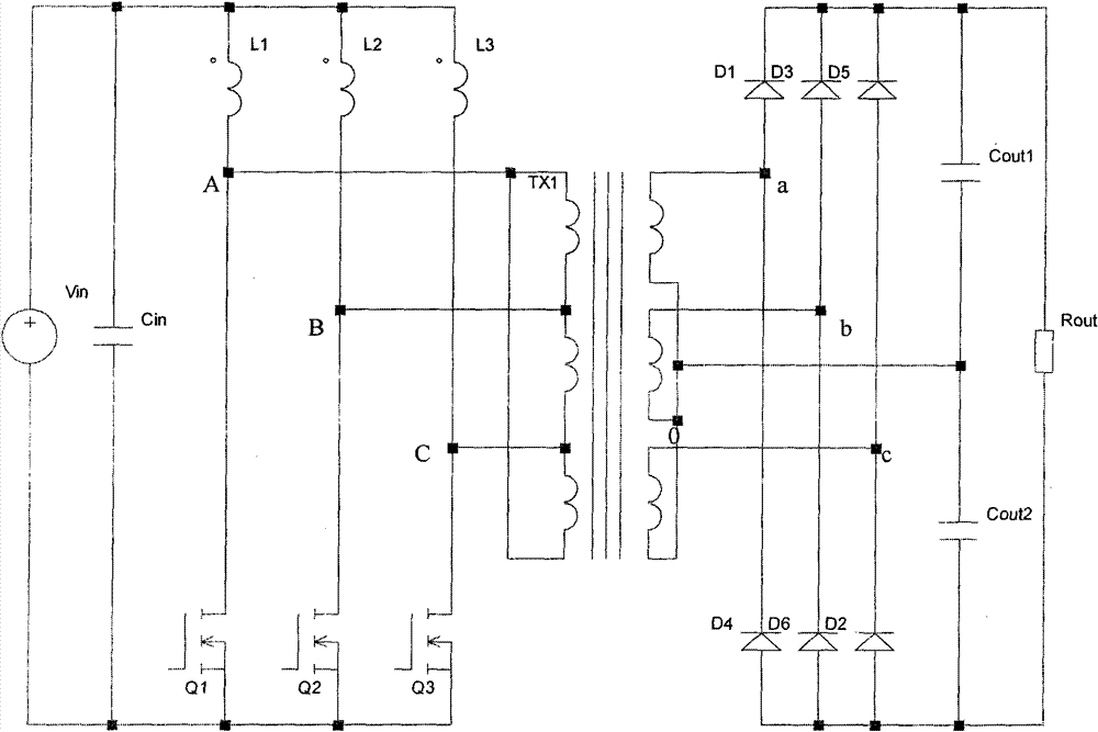
[0010] see figure 1 , the current-fed three-inductance step-up converter of the high-frequency transformer delta-star connection of the present invention includes three power switch tubes Q1, Q2, Q3, and six output rectifier diodes D1, D2, D3, D4, D5, D6 , an input filter capacitor Cin, an output filter capacitor Cout, and a high-frequency three-phase transformer TX1. The primary winding of the high-frequency three-phase transformer is delta-connected and the secondary winding is star-connected. The drain of Q1 is connected to one end of L1 and one end of the primary delta winding of the high-frequency three-phase transformer, the drain of Q2 is connected to one end of L2 and the other end of the primary delta winding of the high-frequency three-phase transformer, and the drain of Q3 is connected to the other end of the primary delta winding of the high-frequency three-phase transformer. One end of L3 is connected to the last end of the delta winding on the primary side of the...


PUM


Abstract

The invention relates to a current feed three-inductor boost converter of a high frequency transformer connected in a delta / Y shape. The boost converter comprises three power switch tubes, three Boost power inductors, an input filter capacitor, an output filter capacitor, six rectifier diodes and a high frequency three-phase transformer, wherein a winding of the high frequency three-phase transformer is connected into a delta / Y shape. In the invention, the output boost is realized by utilizing the intrinsic characteristics of the high frequency three-phase transformer connected in the delta / Yshape; the high gain of an output voltage can be achieved in combination with a proper ratio of winding of the transformer and the current feed three-inductor boost converter; the primary side is an isolated Boost power conversion circuit of the current feed three-inductor, the three-inductor Boost converters are out of phase at 120 degrees, and the effect of the three-phase interleaving parallelconnection can be realized through the current feed three-inductor Boost converter at the primary side and a three-phase rectifying diode at a secondary side, thereby reducing input current ripples and output current ripples, ensuring balance heat distribution of power devices and improving reliability of the converter.

Description

technical field [0001] The invention relates to a DC-DC converter, in particular to a high-frequency transformer delta-star connection current-fed three-inductance step-up converter. Background technique [0002] A conventional full-bridge DC-DC converter includes a high-frequency transformer, four power switch tubes, and four output rectifier diodes, the source of the first power switch tube and the drain of the second power switch tube and the high-frequency One end of the primary winding of the transformer is connected, the source of the third power switch is connected with the drain of the fourth power switch and the other end of the primary winding of the high frequency transformer, the cathode of the first diode is connected with the second diode The anode of the third diode is connected to one end of the secondary winding of the high-frequency transformer, and the cathode of the third diode is connected to the anode of the fourth diode and the other end of the seconda...

Claims


Application Information

Patent Timeline
Patent Type & Authority Patents(China)
IPC IPC(8): H02M3/315H02M1/14
Inventor 谢运祥胡炎申
Owner SOUTH CHINA UNIV OF TECH
Why Eureka
Try Eureka