
Optical intelligent antenna for rapidly moving free space optical communication system

An optical communication system, free space technology, applied in free space transmission, transmission system, coupling of optical waveguides, etc., can solve the problems of communication interruption, unable to match the moving speed with the aiming speed, unable to apply to the FSO system, etc. The effect of intelligence, increasing communication coverage area and improving communication efficiency

Inactive Publication Date: 2010-11-24
XIDIAN UNIV
View PDF7 Cites 16 Cited by
  • Summary
  • Abstract
  • Description
  • Claims
  • Application Information

AI Technical Summary

Problems solved by technology

Although the antenna tracking function of this product can reduce the line-of-sight deviation caused by the slight shaking of the building, it does not have a large-scale fast APT function
Existing products for mobile FSO systems use mechanical tracking and targeting methods, and their tracking and targeting speed cannot match the moving speed between communication targets, or require a long feedback time after obtaining specific coordinate information. These problems This makes it impossible for both communicating parties to perform real-time tracking when they move in a large range, which in turn leads to interruption of communication
Therefore, the existing APT technology is still not suitable for large-scale and fast-moving FSO systems

Method used


Image

  • Optical intelligent antenna for rapidly moving free space optical communication system
  • Optical intelligent antenna for rapidly moving free space optical communication system
  • Optical intelligent antenna for rapidly moving free space optical communication system

Examples


Embodiment 1

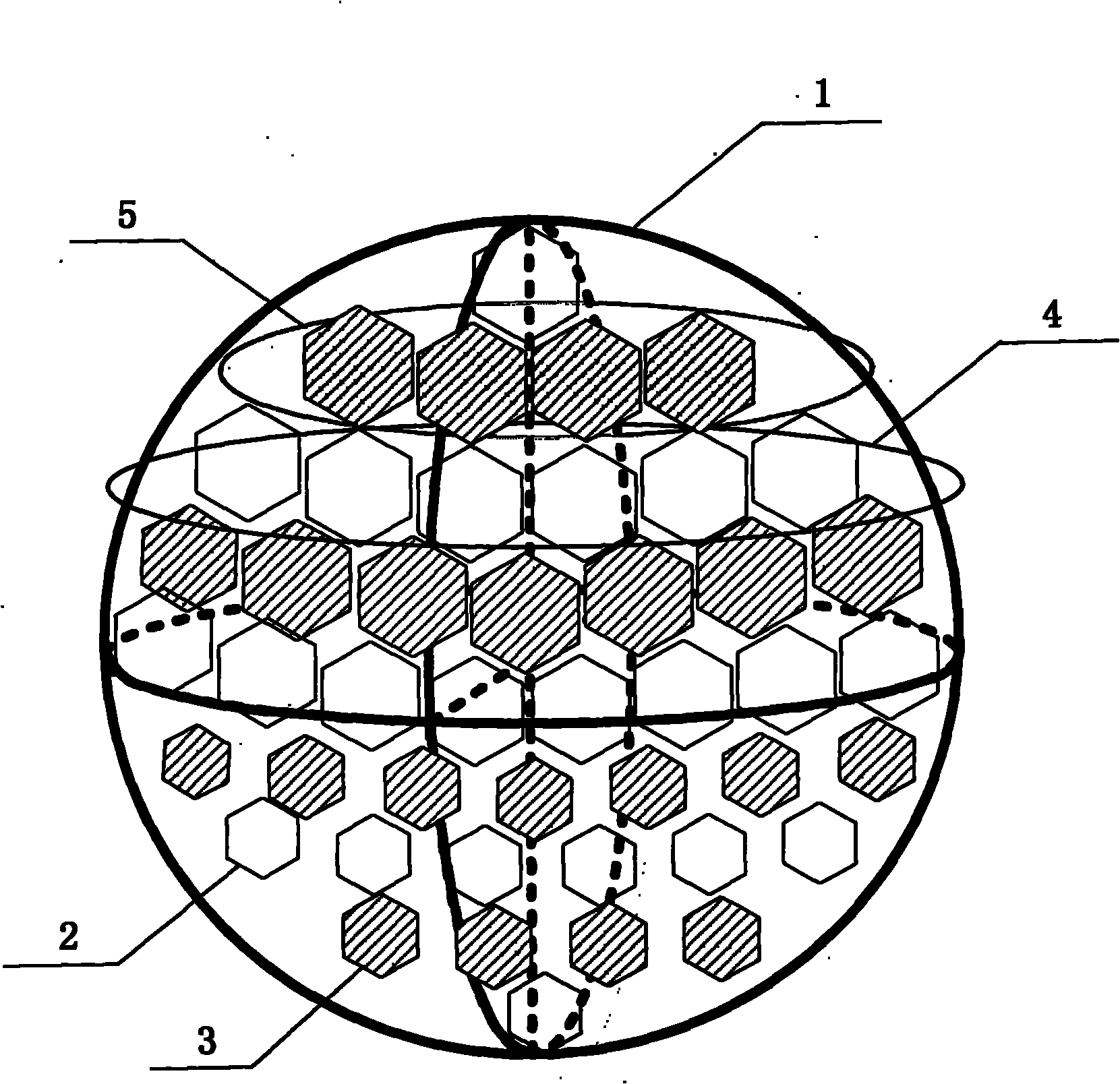
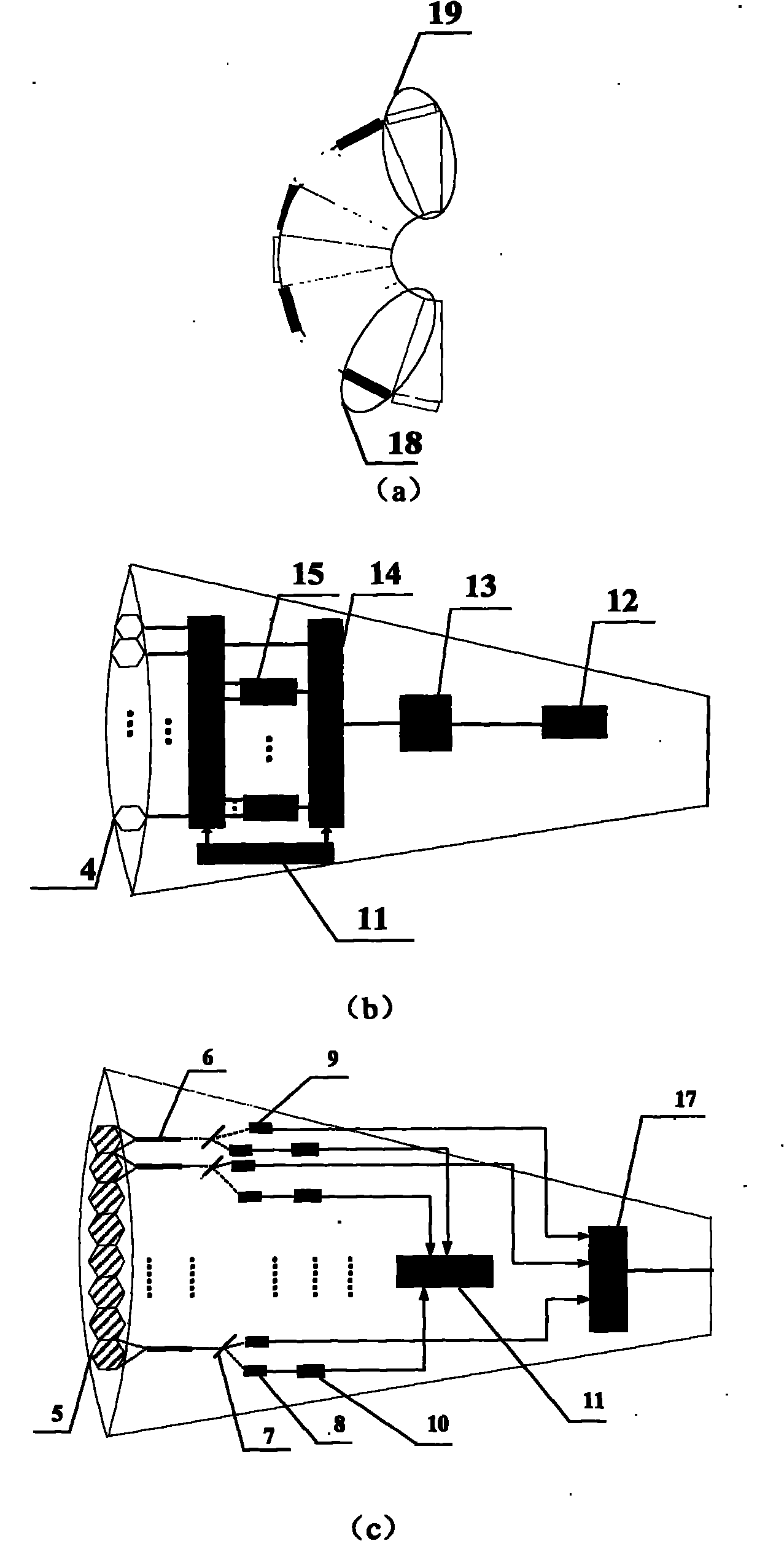
[0034] The present invention is made up of surface structure and internal structure two parts, respectively as figure 1 and figure 2 shown.

[0035] refer to figure 1 , the surface structure of the present invention comprises 5 laser sending arrays and 4 laser receiving arrays, each laser sending array 4 is made up of a plurality of emitting units, and each laser receiving array 5 is made up of a plurality of receiving units; These laser sending arrays and The laser receiving arrays are arranged alternately on a spherical base plate 1 with a radius of 5.093 cm to form a honeycomb laser receiving and receiving array. The first laser transmitting array includes 3 emitting units, arranged in the first row of the spherical base plate 1, and A laser receiving array includes 8 receiving units arranged in the second row of the spherical backplane 1, a second laser sending array includes 12 emitting units arranged in the third row of the spherical backplane 1, and the second laser ...

Embodiment 2

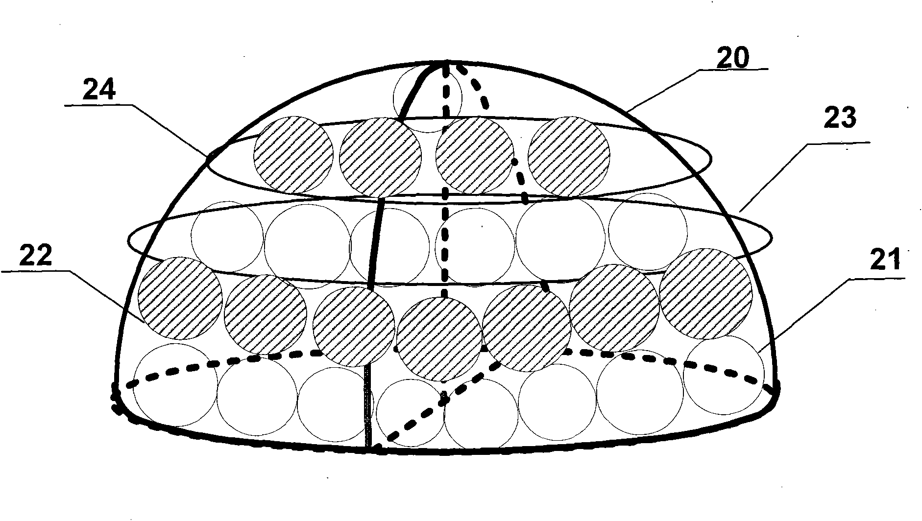
[0040] The present invention is made up of surface structure and internal structure two parts, respectively as image 3 and Figure 4 shown.

[0041] refer to image 3 , the surface structure of the present invention comprises 3 laser sending arrays and 2 laser receiving arrays, each laser sending array 23 is made up of a plurality of emitting units, and each laser receiving array 24 is made up of a plurality of receiving units; These laser sending arrays and The laser receiving arrays are arranged alternately on a hemispherical base plate 20 with a radius of 5.093 cm to form a honeycomb laser receiving and transmitting array, wherein the first laser transmitting array includes 3 emitting units, arranged in the first row of the hemispherical base plate 20 , the first laser receiving array includes 8 receiving units, arranged in the second row of the hemispherical bottom plate 20, the second laser emitting array includes 12 emitting units, arranged in the third row of the hem...


PUM


Abstract

The invention discloses an optical intelligent antenna for rapidly moving a free space optical communication system, aiming to mainly solve the problems of capturing, aligning and tracking a communication target in the conventional free space optical communication system which is moved rapidly point-to-point. The optical intelligent antenna comprises a semi-spherical or spherical bottom plate (1), wherein laser receiving / sending arrays are arranged on the semi-spherical or spherical bottom plate (1); each laser receiving array (5) and each laser sending array (4) are arranged fully on the whole spherical or semi-spherical bottom plate every row to form the laser receiving / sending arrays with a honeycomb structure; and each laser receiving / sending array corresponds to a group of internal structure units which are embedded in a cavity body of the spherical or semi-spherical bottom plate so as to correspondingly adjust optical wave beams through a device in the structure units under the condition of space division time multiplexing and angle multiplexing. The optical intelligent antenna increases the communication coverage area, can automatically control the optical wave beams of a transmitting unit rapidly and in real time according to the movement of the communication target, and can be used in the field of wireless laser communication.

Description

technical field [0001] The invention belongs to the technical field of wireless laser communication, and relates to a communication antenna, in particular to an optical smart antenna suitable for a fast-moving free-space optical communication FSO system. Background technique [0002] As a new type of broadband wireless communication technology, the fast-moving free-space optical communication FSO system has attracted much attention due to its many unparalleled advantages. Compared with optical fiber communication, it does not need to lay optical cables, is cheap, has a short construction period, and has It can reach the level of optical fiber communication; compared with microwave communication, the bandwidth is 1 to 2 orders of magnitude higher than microwave, and no frequency application is required. At the same time, wireless optical communication equipment has a series of advantages such as flexible networking, no electromagnetic interference, good concealment, excellent...

Claims


Application Information

Patent Timeline
Patent Type & Authority Applications(China)
IPC IPC(8): H04B10/10G02B6/42H04B10/11
Inventor 尚韬杨玥黄果刘增基李曦熊桂芳岳鹏
Owner XIDIAN UNIV
Learn More