Waste water treatment device and process for synchronously removing nitrogen and phosphorus of sludge concentration microenvironment

A technology for synchronous denitrification and phosphorus removal and sewage treatment equipment, which is applied in the field of sewage treatment and can solve problems such as increased investment and operating costs, complicated operation, and difficulty in further improving the denitrification effect

Active Publication Date: 2010-12-01
BEIJING DRAINAGE GRP CO LTD
View PDF3 Cites 4 Cited by
  • Summary
  • Abstract
  • Description
  • Claims
  • Application Information

AI Technical Summary

Problems solved by technology

The traditional A/A/O process mainly has the following problems: 1. Insufficient carbon source affects the phosphorus release in the anaerobic pond and the denitrification process in the anoxic pond
2. Lower activated sludge concentration affects the stability of effluent ammonia nitrogen
3. The processing load is limited by the sludge settling performance. Due to the slow speed of sludge settling, the processing load cannot be further increased
4. The denitrification effect is difficult to further improve due to the limitation of the reflux flow of nitrification liquid, that is, the internal reflux, and increasing the internal reflux will lead to insufficient carbon sources
The traditional A/A/O process often solves the problem of insufficient carbon sources by adding external carbon sources such as methanol, adding fillers in the aeration tank and increasing the sludge

Method used


Image

  • Waste water treatment device and process for synchronously removing nitrogen and phosphorus of sludge concentration microenvironment
  • Waste water treatment device and process for synchronously removing nitrogen and phosphorus of sludge concentration microenvironment
  • Waste water treatment device and process for synchronously removing nitrogen and phosphorus of sludge concentration microenvironment

Examples


Embodiment Construction

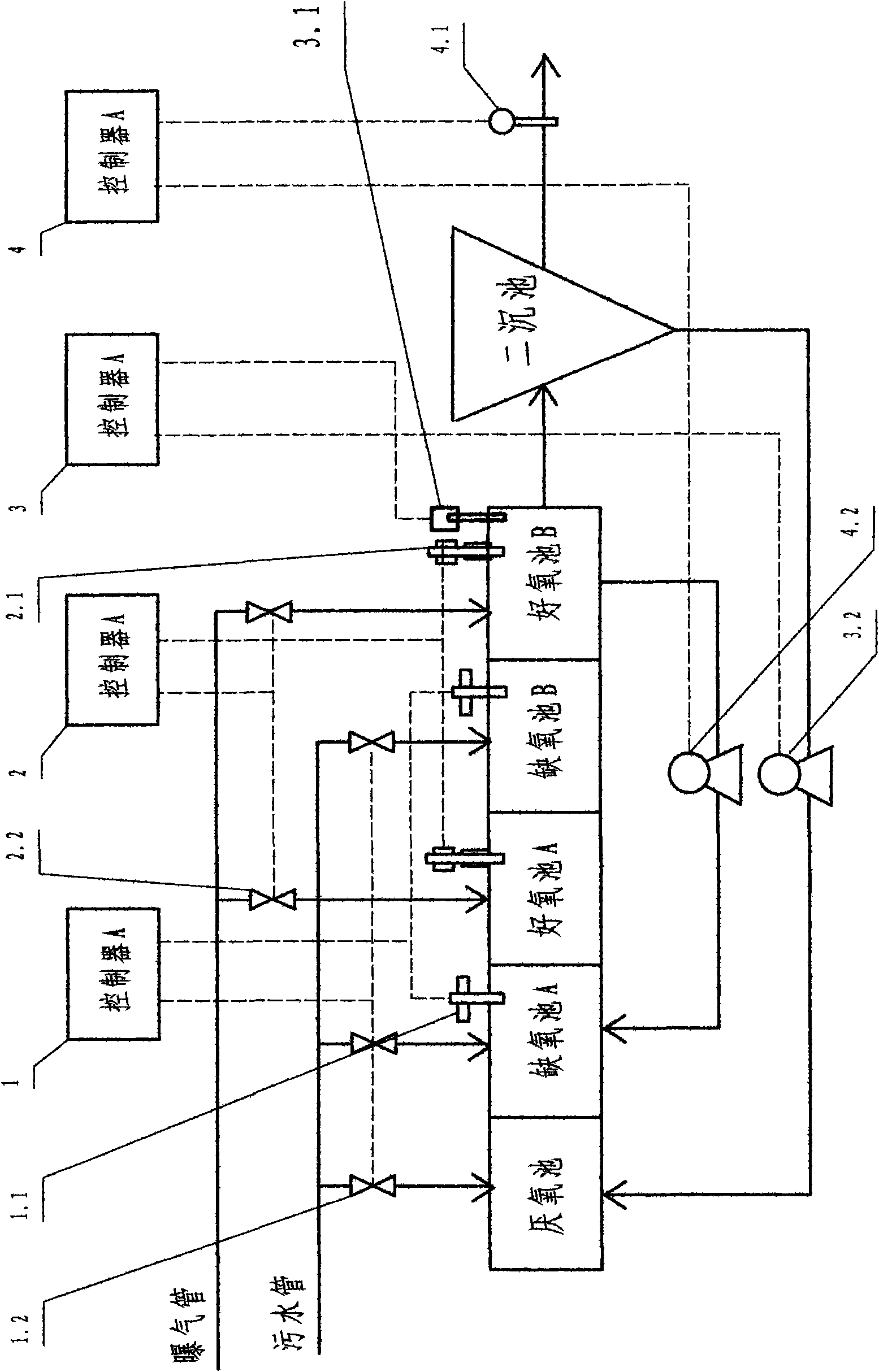
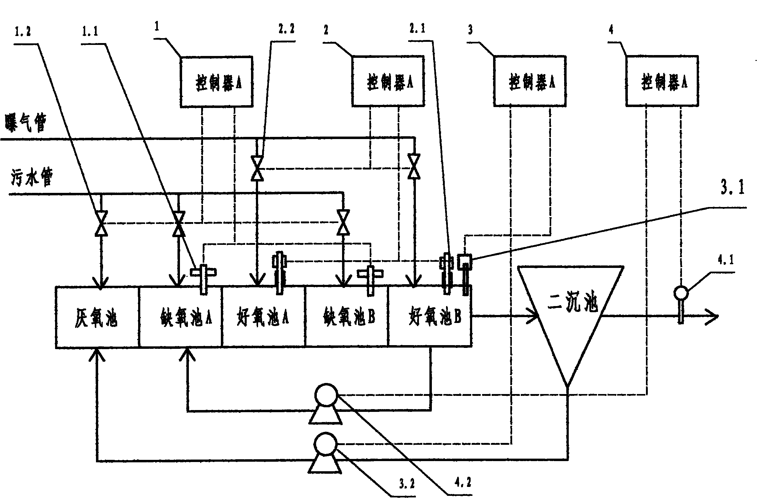
[0019] Attached below figure 1 The present invention is further described with examples:

[0020]High sludge concentration microenvironment synchronous denitrification and dephosphorization sewage treatment device, equipped with anaerobic tank, anoxic tank, aerobic tank and secondary sedimentation tank, nitrifying liquid return, internal return pump and pipeline which are arranged and connected in sequence. , sludge return, namely external return pump and pipeline, dissolved oxygen control device and influent carbon source distribution device; there are two anoxic pools and aerobic pools respectively, and they are arranged in sequence as anoxic pool A, aerobic pool A, anoxic tank B, aerobic tank B, the front is connected to the anaerobic tank, and the rear is connected to the secondary sedimentation tank; the internal return pump and the pipeline are: from the aerobic tank B to the anoxic tank A The nitrifying liquid reflux pipe Circuit and frequency conversion control adjust...


PUM


Abstract

The invention relates to a waste water treatment device for synchronously removing nitrogen and phosphorus of sludge concentration microenvironment, comprising an anaerobic pond, two anoxic ponds, two oxidation ponds, two sedimentation ponds, an internal reflux pump, an external reflux pump, pipelines, a dissolved oxygen control device, an inlet water carbon source distribution device, an internal reflux positive displacement pump and an external reflux positive displacement pump; the dissolved oxygen control device is provided with a dissolved oxygen controller B and a dissolved oxygen concentration meter; the inlet water carbon source control device is provided with a nitrate nitrogen-concentration controller A and a nitrate nitrogen concentration meter; and the waste water treatment device is further provided with an internal reflux control device and an external reflux control device. The process utilizing the waste water treatment device comprises the following steps of setting control data of a controller C of the internal reflux pump A; setting control data of a controller D of the external reflux pump B; setting control data of the dissolved oxygen controller B and the nitrate nitrogen concentration controller A; and opening an inlet water gate and all machines and electric control parts for running. The invention is suitable for waste water treatment, and has simple process, energy saving, low cost and high water outlet efficiency and good quality.

Description

technical field [0001] The invention belongs to a sewage treatment technology, in particular to an anaerobic-anoxic-aerobic type, namely the improved equipment and process of the A / A / O sewage treatment technology. Background technique [0002] At present, the traditional A / A / O wastewater treatment process is a widely used biological denitrification and phosphorus removal process, which solves the problem of wastewater denitrification and phosphorus removal to a certain extent. With the increasing awareness of environmental protection in the society and the increasing shortage of water resources, the requirements for the quality of effluent from sewage treatment plants are getting higher and higher. The traditional A / A / O process mainly has the following problems: 1. Insufficient carbon source affects the phosphorus release in the anaerobic tank and the denitrification process in the anoxic tank. 2. Lower activated sludge concentration affects the stability of effluent ammoni...

Claims


Application Information

Patent Timeline
IPC IPC(8): C02F3/30
Inventor 王佳伟甘一萍李魁晓蒋勇周军赵颖
Owner BEIJING DRAINAGE GRP CO LTD
Why Eureka
Try Eureka