

Blow pipe for copper smelting furnace and manufacturing method thereof
A technology of copper smelting furnace and manufacturing method, which is applied to furnaces, reverberatory furnaces, furnace components, etc., which can solve problems such as low service life, melting loss and erosion of refractory layer, consumption of blowing pipe, etc., and achieve long service life and high strength.
- Summary
- Abstract
- Description
- Claims
- Application Information
AI Technical Summary
Problems solved by technology
Method used
Image

Examples
Embodiment 1
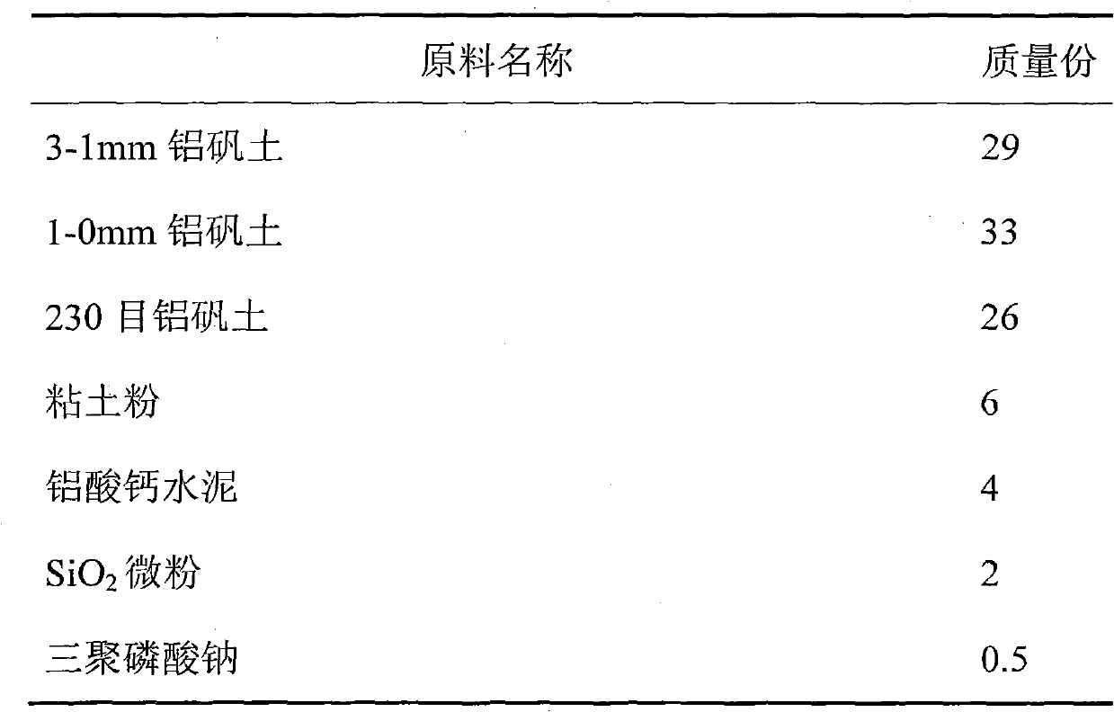
[0041] The raw materials contained in the refractory pipe of the copper smelting furnace blowpipe are shown in Table 1:
[0042] Table 1 Raw materials contained in the refractory tube of the copper smelting furnace blowpipe
[0043]
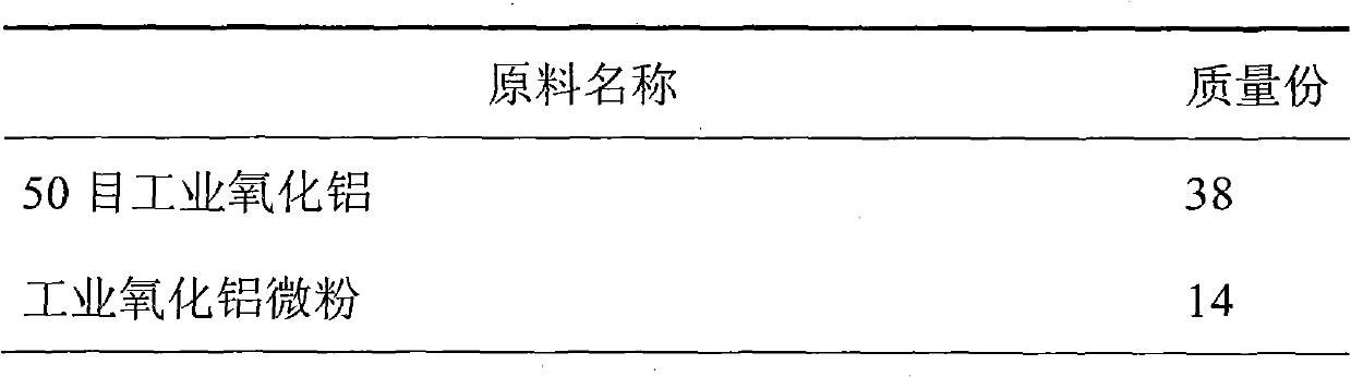
[0044] The composition of the raw materials in the refractory mud is shown in Table 2:
[0045] Table 2 Raw material composition of refractory mud
[0046]
[0047]
[0048] The manufacture method of this kind of copper smelting blowpipe comprises the following steps:
[0049] 1) Weigh the raw materials according to the mass parts described in Table 1, premix with a cone mixer, add an appropriate amount of water after premixing and place in a wheel mill to mix the materials evenly, and keep the materials for more than 24 hours;
[0050] 2) The trapped mud enters the vacuum extruder and is extruded into a wet billet, which is naturally placed for more than 48 hours and the billet is trimmed, and then the billet is dried until the moistu...
Embodiment 2
[0055] The raw materials contained in the copper smelting blowpipe refractory pipe are shown in Table 3:
[0056] Table 3 Raw materials contained in the refractory pipe of the copper smelting furnace blowpipe
[0057]
[0058]
[0059] The composition of raw materials in the refractory mud is shown in Table 4:
[0060] Table 4 Raw material composition of refractory mud
[0061]
[0062] Copper smelting blowpipe is prepared in the present embodiment, and its steps are identical with embodiment 1.
Embodiment 3
[0064] The raw materials contained in the copper smelting blowpipe refractory pipe are shown in Table 5:
[0065] Table 5 Raw materials contained in the refractory pipe of the copper smelting furnace blowpipe
[0066]
[0067]
[0068] The composition of the raw materials in the refractory mud is shown in Table 6:
[0069] Table 6 Raw material composition of refractory mud
[0070]
[0071] Copper smelting blowpipe is prepared in the present embodiment, and its steps are identical with embodiment 1.
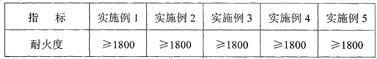
PUM
| Property | Measurement | Unit |
|---|---|---|
| Refractoriness | aaaaa | aaaaa |
| Compressive strength | aaaaa | aaaaa |
Abstract
Description
Claims
Application Information