Centrifuge used in multi-parameter complex test environment

A compound test and multi-parameter technology, which is applied in the field of centrifuges, can solve the problems of difficult installation and compound test, etc., and achieve the effect of small space occupation of the machine body, reduction of mass and moment of inertia, and increase of bearing weight

Inactive Publication Date: 2010-12-15
ZHEJIANG UNIV
View PDF5 Cites 13 Cited by
  • Summary
  • Abstract
  • Description
  • Claims
  • Application Information

AI Technical Summary

Problems solved by technology

This arm structure makes it difficult to install more devices on the arm, and it is also difficult to conduct composite tests in more environments

Method used


Image

  • Centrifuge used in multi-parameter complex test environment
  • Centrifuge used in multi-parameter complex test environment
  • Centrifuge used in multi-parameter complex test environment

Examples


Embodiment 1

[0049] refer to Figure 1-9

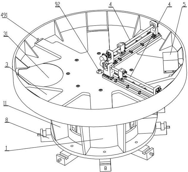
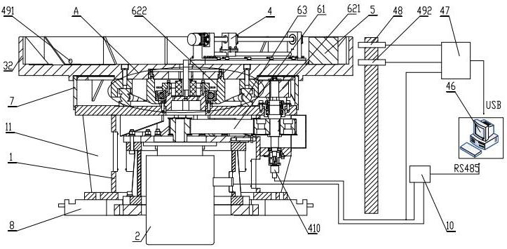
[0050] A centrifuge used in a multi-parameter composite test environment, including a base 1, a drive motor 2 fixed on the base, an arm 3 carrying a composite parameter test device, and transmitting the power of the drive motor 2 to The transmission mechanism of the machine arm 3, the static balance mass 5 fixed on the machine arm and the dynamic balance actuator 4 installed on the machine arm 3 to realize self-adaptive dynamic balance;

[0051] Described machine arm 3 is disc-shaped, and described machine arm 3 is evenly provided with web 31, and described composite parameter test device is installed on described web 31;

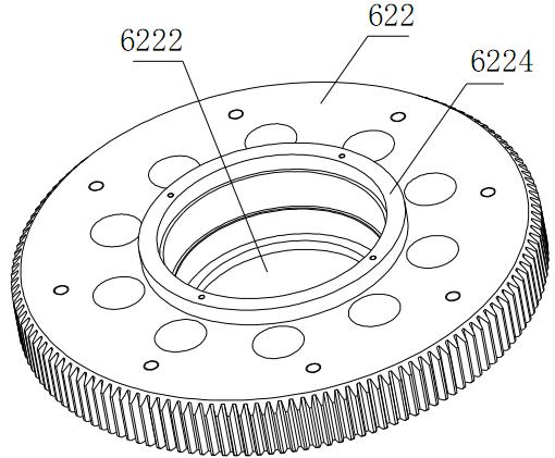
[0052] The transmission mechanism includes a belt transmission mechanism 61 connected to the output shaft of the drive motor 2 and a gear mechanism connected to the machine arm 3; The gear 621 and the large gear 622 affixed to the machine arm 3;

[0053] The upper surface of the large gear 622 is connected with the bottom su...

Embodiment 2

[0064] refer to Figure 9

[0065] The difference between this embodiment and Embodiment 1 is that: the through hole 6222 of the large gear 622 is provided with a rotary air supply for supplying air to each test device, and the air pipe on the arm can follow the rotation of the arm 3 Mechanism, the rotary air supply mechanism includes a hollow conductive slip ring 91 and a rotary joint 92 connecting the gas delivery pipe with an external air source, and the rotary joint 92 is located inside the conductive slip ring 91;

[0066] The fixed ring of the conductive slip ring 91 is affixed to a mounting base 93, the mounting base 93 is fixed to the base 1, the moving ring of the conductive slip ring 91 is connected to the large gear 622 Linkage; the moving ring of the conductive slip ring 91 is fixedly connected to a rotating flange 94, and the rotating flange 94 is fixedly connected to the large gear 622;

[0067] The fixed coil of the rotary joint 92 is fixedly connected to the ...

Embodiment 3

[0071] refer to Figure 10 , 12 、13

[0072] The difference between the present invention and the second embodiment is that the dynamic balance actuator 4 includes a dynamic balance execution unit that adjusts its dynamic balance mass 44 along two directions, and the dynamic balance execution unit includes The base 41 on the machine arm 3, the guide rail 42 fixed on the base 41, the slider 43 slidingly connected with the guide rail 42 and the slider 43 that pushes the slider 43 to reciprocate along the guide rail Dynamic balance transmission mechanism, the dynamic balance mass block 44 is affixed to the slider 43, and the two adjustment directions of the dynamic balance execution unit are vertical;

[0073] Described machine arm 3 is provided with collecting device that collects the periodical vibration response of machine arm 3 caused by unbalance, and described collecting device can obtain the amplitude and phase of the vibration response caused by different balance quanti...


PUM


Abstract

The invention discloses a centrifuge used in a multi-parameter complex test environment. The centrifuge comprises a stand, a driving motor, an arm, a transmission mechanism and a dynamic balance executing mechanism, wherein the arm is provided with a web plate; the transmission mechanism comprises a belt transmission mechanism and a gear mechanism; the gear mechanism comprises a pinion which is coaxial with a driven pulley and a bull gear which is fixedly connected with the arm; the upper surface of the bull gear is contacted with the bottom surface of the arm; the lower surface of the bull gear is provided with an annular groove for accommodating a thrust ball bearing capable of providing axial support for the bull gear; the bull gear is connected with the stand through the thrust ball bearing; a gap is reserved between the lower surface of the bull gear and the stand; the bull gear is provided with a through hole; the bottom of the through hole is extended inwards to form a step for arranging an angular contact ball bearing; a cover plate which is fixedly connected with the stand to compress the angular contact ball bearing is arranged above the angular contact ball bearing; and the driving motor and the transmission mechanism are arranged in the stand. The centrifuge has the advantages of small space occupied by the body, high capacity of the arm and capability of carrying various environmental chambers and realizing adaptive dynamic balance of the arm.

Description

technical field [0001] The invention relates to a centrifuge used in a multi-parameter compound test environment. technical background [0002] With the development of science and technology, especially aerospace technology, the reliability requirements for electromechanical components are getting higher and higher. The application environment of these components and products is becoming more and more complex. For example, when a spacecraft is launched and re-enters the atmosphere, it will be affected by complex environmental factors such as linear acceleration, temperature, vibration, and noise. In order to ensure that the spacecraft can work normally in flight, its surface materials and internal electronic equipment must withstand this external impact. Environmental testing with the advantages of low cost, high efficiency, controllability and repeatability is of great significance for detecting the response of products to environmental impact. [0003] The linear acceler...

Claims


Application Information

Patent Timeline
Patent Type & Authority Applications(China)
IPC IPC(8): G01M7/08G01M1/38G01N17/00
Inventor 沈润杰荣左超何闻贾叔仕
Owner ZHEJIANG UNIV
Why Eureka
Try Eureka