Metal halide lamp power supply and method for lighting metal halide lamp

A halogen lamp and metal technology, applied in the field of metal halide lamp power supply and lighting the metal halide lamp based on the metal halide lamp power supply, can solve the problem of unstable power frequency transformer power supply, inconvenient installation, transportation and maintenance, and low efficiency of transformer power supply and other issues, to achieve significant power-saving effects, light weight, and low loss

Active Publication Date: 2010-12-15
深圳优卫乐得科技有限公司
View PDF10 Cites 4 Cited by
  • Summary
  • Abstract
  • Description
  • Claims
  • Application Information

AI Technical Summary

Problems solved by technology

Although the power frequency transformer power supply can achieve the effect of lighting the metal halide lamp, the power frequency transformer power supply is very unstable during the working process (changes with the change of the power grid) and cannot be adjusted (the transformer parameter design is as much as it is)
Moreover, since the power frequency transformer power supply is a single-phase 380V input, the three-phase imbalance is artificially caused; and the efficiency of the transformer power supply itself is also very low, only about 50%, resulting in a grid power factor of ≤0.5, which greatly wastes energy , reducing the efficiency of using
In addition, the transformer is large and heavy, and there are many inconveniences in installation, transportation and maintenance.

Method used


Image

  • Metal halide lamp power supply and method for lighting metal halide lamp
  • Metal halide lamp power supply and method for lighting metal halide lamp
  • Metal halide lamp power supply and method for lighting metal halide lamp

Examples


Embodiment Construction

[0022] The present invention will be described in detail below in conjunction with the accompanying drawings.

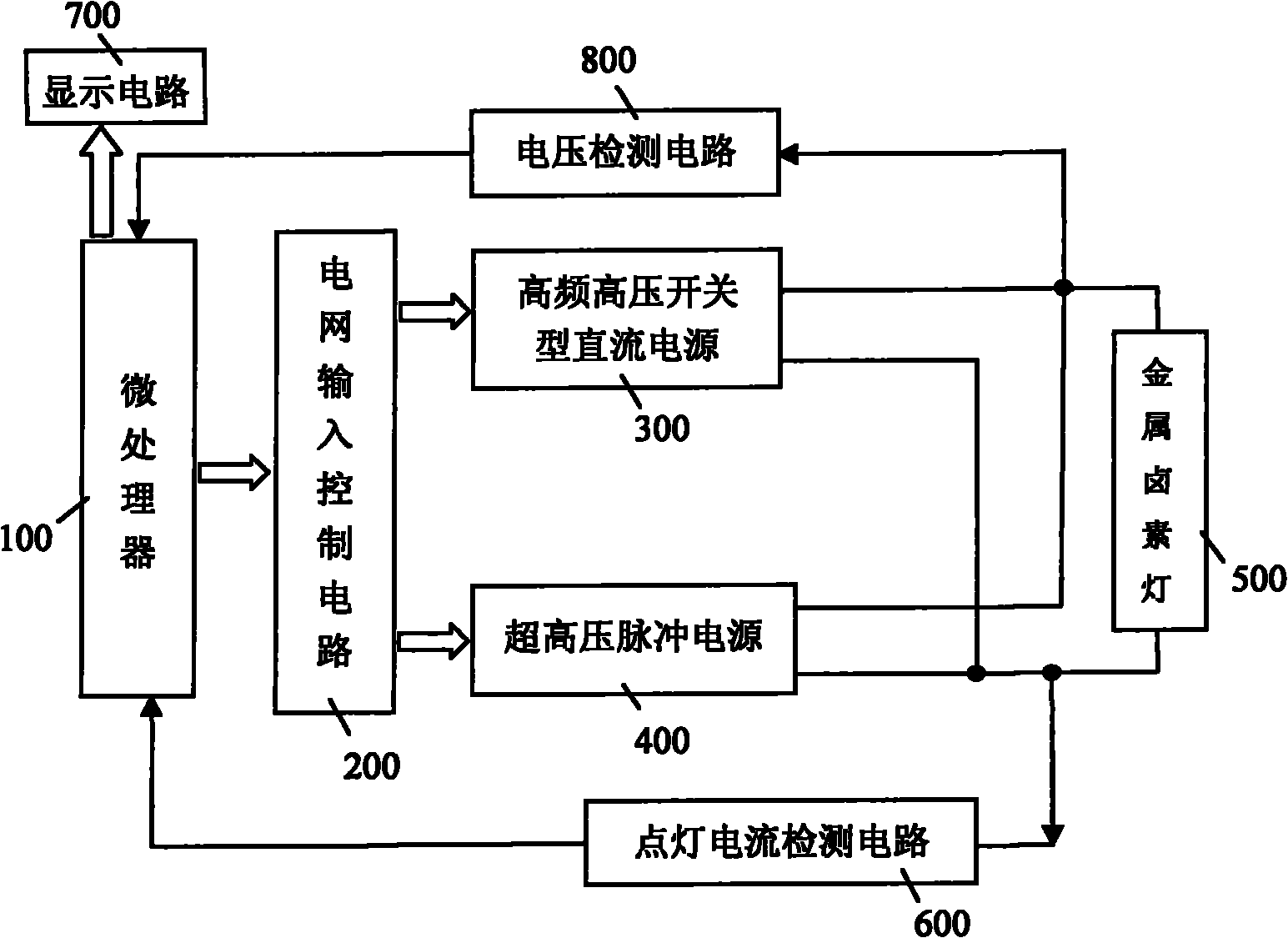
[0023] like figure 1 , the metal halide lamp power supply of the present invention includes a microprocessor 100 (such as Image 6 ), a high-frequency high-voltage switching DC power supply 300, an ultra-high voltage pulse power supply 400, a lighting current detection circuit 600, and a voltage detection circuit 800. The signal output terminal of the microprocessor 100 is respectively connected to the input terminal of the high-frequency high-voltage switching DC power supply 300 and the input terminal of the ultra-high voltage pulse power supply 400 via the grid input control circuit 200. The high-frequency high-voltage switching DC power supply 300 The output end of the ultra-high voltage pulse power supply 400 is connected to the metal halide lamp 500, that is, the high-frequency high-voltage switching DC power supply 300 and the ultra-high voltage pulse power s...


PUM


Abstract

The invention discloses a metal halide lamp power supply and a method for lighting a metal halide lamp. The power supply comprises a microprocessor, wherein a signal output end of the microprocessor is connected with input ends of a high-frequency high-voltage switching direct current power supply and a super-high voltage pulse power supply through a power grid input control circuit respectively;the output ends of the high-frequency high-voltage switching direct current power supply and the super-high voltage pulse power supply are connected with the metal halide lamp; a lighting current detection circuit feeds back a detected current detection signal to the microprocessor; and a voltage detection circuit feeds back a detected voltage signal to the microprocessor. The method for lightingthe metal halide lamp comprises the following steps of: preparing the high-frequency high-voltage switching direct current power supply; when the output voltage of the high-frequency high-voltage switching direct current power supply is increased to a rated value, lighting the metal halide lamp by the super-high voltage pulse power supply, wherein the high-frequency high-voltage switching direct current power supply is used as a working power supply; and cutting off the input voltage of the super-high voltage pulse power supply. By the method for lighting the metal halide lamp of the invention, the metal halide lamp can be quickly and safely lighted; and the power supply of the invention is suitable for photo-curing equipment and has the advantages of high efficiency, energy conservation,low cost and the like.

Description

technical field [0001] The invention relates to a metal halide lamp power supply and a metal halide lamp lighting method, in particular to a metal halide lamp power supply and a method for lighting the metal halide lamp based on the metal halide lamp power supply. Background technique [0002] The metal halide lamp used in the current photocuring equipment is a new generation of cold light source energy-saving lamp, and its ultraviolet radiation efficiency can reach more than 93%. The high-purity quartz tube is filled with iodide containing mercury, argon, gallium, and iodine of iron. Compounds and some rare metal halides. The metal halide lamp is widely used in circuit board (PCB) manufacturing, UV machine, printing, etching, medical and other industries, such as curing of UV ink and UV paint, PCB dry film, wet film, green solder mask, PCB board exposure Wait. [0003] The metal halide lamp for light curing equipment requires a high power supply voltage (500V-5000V) and a...

Claims


Application Information

Patent Timeline
Patent Type & Authority Applications(China)
IPC IPC(8): H05B41/16
Inventor 兰卫国
Owner 深圳优卫乐得科技有限公司
Why Eureka
Try Eureka