Device for sterilizing and purifying air in tunnel

A tunnel air and purifier technology, applied in the directions of disinfection, irradiation, deodorization, etc., can solve the problems of high energy consumption, high maintenance cost, inconvenient installation and use, etc., achieve compact overall structure, prolong working life, avoid easily damaged effect

Active Publication Date: 2013-12-25
ZHEJIANG TIANQING ENVIRONMENTAL PROTECTION TECH CO LTD
View PDF1 Cites 1 Cited by
  • Summary
  • Abstract
  • Description
  • Claims
  • Application Information

AI Technical Summary

Problems solved by technology

However, with so many heating chambers and heating units, the processing air volume reaches 360,000-720,000 M 3 It is conceivable that the power consumption per hour is huge; at the same time, the temperature control of the long-term measurement and control module cannot be foolproof
In addition, the electrostatic precipitator is flushed after one week; a large number of catalysts and activated carbon must be replaced every 3-12 months
This is not only huge equipment, occupying a lot of land, high energy consumption, high maintenance costs, but also inconvenient to install and use.

Method used


Image

  • Device for sterilizing and purifying air in tunnel
  • Device for sterilizing and purifying air in tunnel
  • Device for sterilizing and purifying air in tunnel

Examples


Embodiment 1

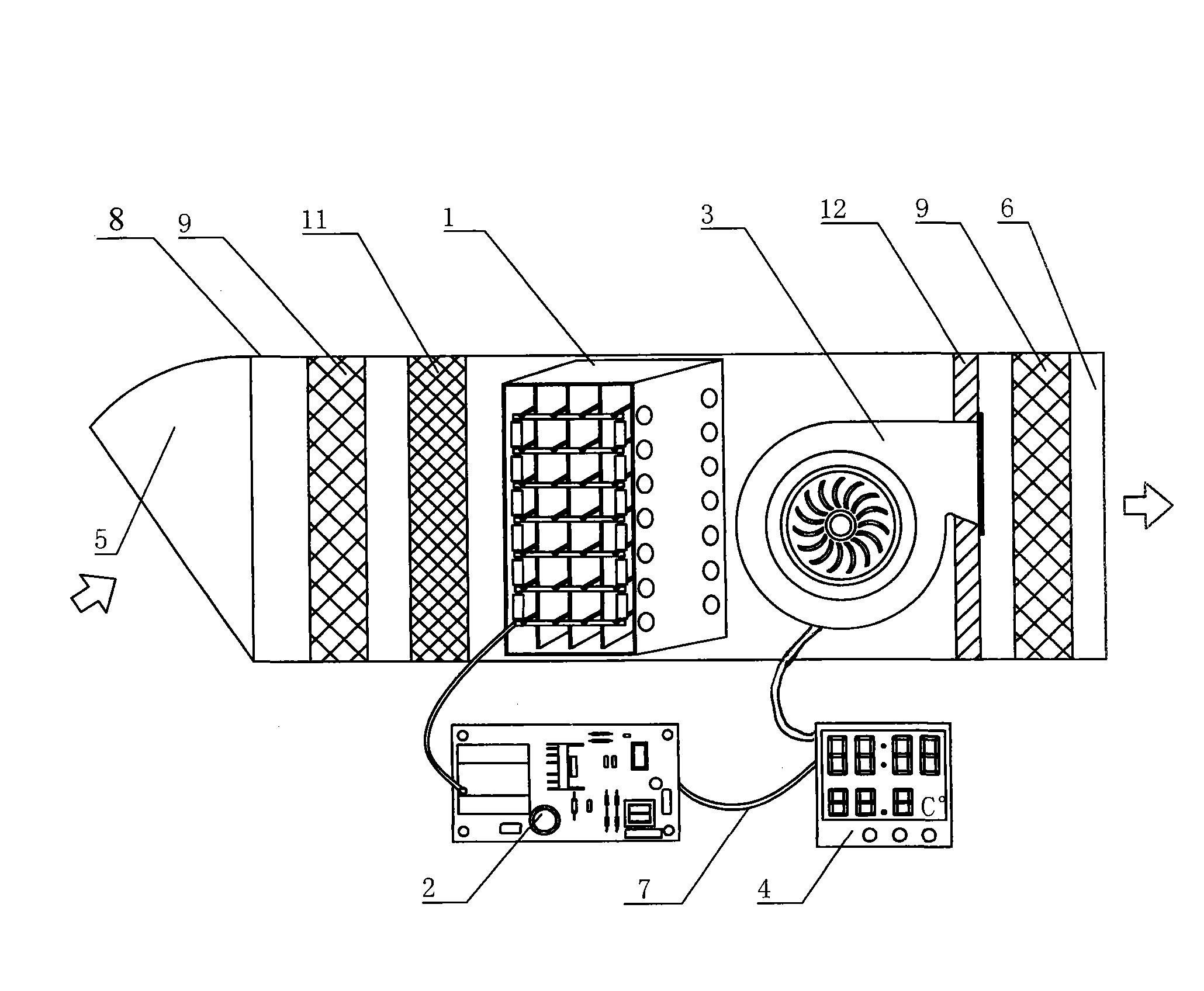
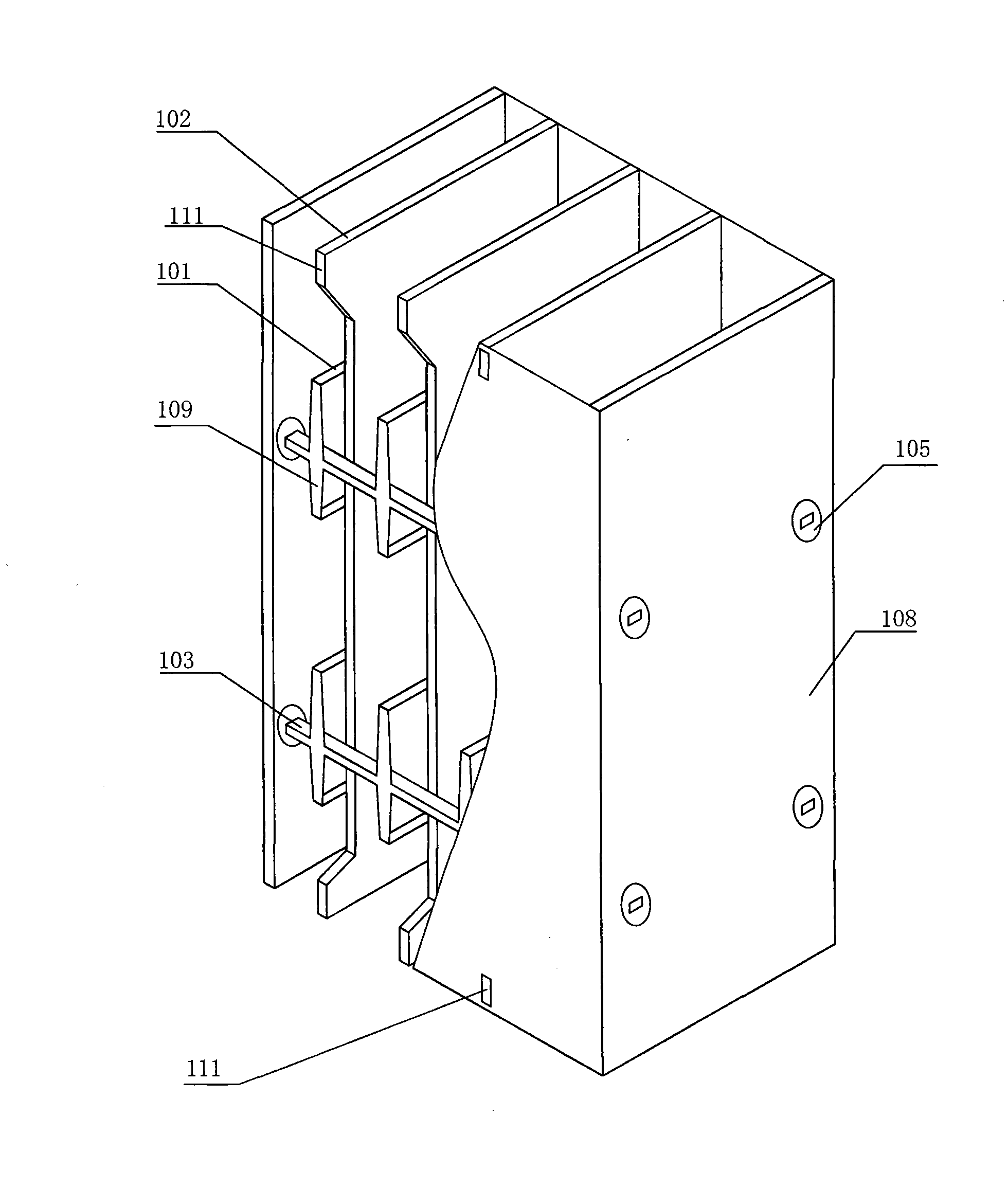
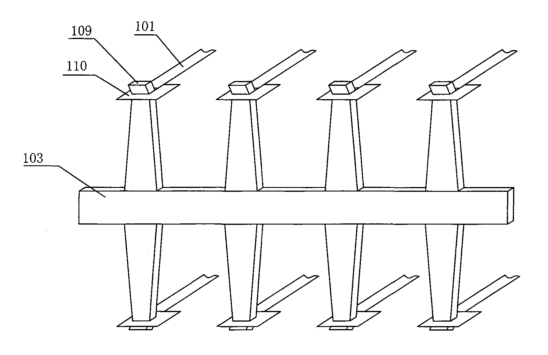
[0058] figure 1 It is a schematic diagram of the cross-sectional structure of the tunnel air disinfection purifier of the present invention; figure 2 It is a three-dimensional structure diagram of a plasma reactor half section of the present invention; image 3 It is a structural schematic diagram of the conductive rail for preventing micro-discharge of the present invention. The present invention comprises a plasma reactor 1, a pulse power supply 2, a fan assembly 3, a controller 4, an air inlet 5, an air outlet 6 and a casing 8, the air inlet 5 and the air outlet 6 are each provided with an air filter 9, and the plasma reaction The controller 1 and the fan assembly 3 are arranged in the air flow, and the two output terminals of the controller 4 are electrically connected with the pulse power supply 2 and the power control terminals of the fan assembly 3 by wires 7 respectively. The described reactor 1 is provided with a positive electrode 101 and a negative electrode 102....

Embodiment 2

[0063] Figure 4 It is the electrical principle diagram of the pulse power supply of the present invention; Figure 5 It is a structural schematic diagram of the pulse transformer of the present invention; Image 6It is the pulse transformer circuit diagram of the present invention. As shown in the figure: the pulse power supply 2 is provided with an EMC filter 201, a rectifier circuit 202, a filter circuit 203, a pulse generator 204, and a pulse transformer 205 for electrical connection in sequence, and the positive pole of the high-voltage output terminal of the pulse transformer 205 is connected to the plasma reaction The positive electrode 101 of the reactor 1, the negative electrode of the high voltage output terminal is connected to the negative electrode 102 of the plasma reactor 1 and grounded. The oscillator, error amplifier, PWM comparator and switching tubes are provided in the pulse generator 204, and the pulse transformer 205 and the switching tubes in the pulse...

Embodiment 3

[0067] The negative electrode 102 according to the present invention is provided with a protruding negative electrode fixing pin 111 at the upper and lower ends of the reactor shell 108, and the corresponding part of the reactor shell 108 is provided with grooves for docking and fastening. The thickness of the negative electrode aluminum plate is set at 1-2.0 mm, the surface is oxidized, the working life is long, and the appearance is bright. Alternatively, the thickness of the stainless steel plate used as the negative electrode 102 is 0.5-1.5 mm. Welding technology is used in the implementation, and there is warping phenomenon. There will be assembly errors when bending the negative electrode 102 and twisting the nails, and the process is not as good as this preferred embodiment. Both sides of the negative electrode 102 are coated with nano-scale TiO 2 It is an anatase catalyst with a band gap energy of 3.2eV.

[0068] The positive electrode 101 of the present invention i...


PUM

PropertyMeasurementUnit
thicknessaaaaaaaaaa
thicknessaaaaaaaaaa
thicknessaaaaaaaaaa

Abstract

The invention belongs to the technical field of air sterilization and purification and particularly relates to a device for sterilizing and purifying the air in a tunnel. The device comprises a plasma reactor, a pulse power supply, a fan component, a controller, an air inlet, an air outlet and a housing, wherein the positive electrode in the plasma reactor is manufactured into a component by arranging a plurality of oxidation-resistant metal belts in the same plane in a way that the metal belts are parallel and equidistant, and the negative electrode therein is made from aluminum plates subjected to surface oxidation treatment and application of nano-scale TiO2 on both sides thereof; the device further comprises a plurality of micro-discharge-resisting conductor rails made from aluminum rods or stainless steel bars; and the two ends of the positive electrode are respectively fixed at the top end of a convex part of the corresponding conductor rail. The plasma and free radicals of the invention are capable of achieving the dual purposes of sterilization and disinfection, degrading contaminants and absorbing particulate matters; and the device of the invention has the advantages of simple structure, convenient installation, energy conservation, good reliability and long service life. The device of the invention is mainly applicable in tunnels, subways and underground garages and also applicable to the air sterilization and purification in families and public places, such as movie theaters, trains, cars, ships and the like.

Description

Technical field: [0001] The invention belongs to the technical field of air disinfection and purification, and in particular relates to a tunnel air disinfection purifier. Background technique: [0002] At present, the air pollutants in the tunnel are mainly exhaust gas and dust from motor vehicles, including CO, NO x and HC. Recently, someone at the entrance of the Dongshan Tunnel in Dinghai reported: "The dust and exhaust gas in the tunnel is relatively serious, especially the exhaust gas from large diesel locomotives. The tunnel is equipped with 2 groups of 8 fans for one-way exhaust. The exhaust fan can discharge exhaust gas and dust, but the fan itself has disadvantages: loud noise and high power consumption. Other similar problems often occur. [0003] For this reason, people in the industry carry out research and improvement. For example, the application number is 200810201240.2, the application date: 2008.10.16, and the invention name is "Tunnel Air Pollutant Pur...

Claims


Application Information

Patent Timeline
Patent Type & Authority Patents(China)
IPC IPC(8): A61L9/00A61L9/20A61L9/22A61L101/02
Inventor 周云正陈爱芝
Owner ZHEJIANG TIANQING ENVIRONMENTAL PROTECTION TECH CO LTD
Why Eureka
Try Eureka