
Piezoelectric Power Converter

A power converter, piezoelectric technology, applied in the direction of converting irreversible AC power input to DC power output, etc., can solve the problems of low capacitance, insufficient voltage resistance of capacitors, and fire.

Active Publication Date: 2016-03-30
MIDAS WEI TRADING +1
View PDF6 Cites 0 Cited by
  • Summary
  • Abstract
  • Description
  • Claims
  • Application Information

AI Technical Summary

Problems solved by technology

[0003] In order to meet these technical requirements, designers must use higher efficiency power supplies. However, in the circuit of general power converters, general capacitors are used in series or in parallel with inductors for resonance effect. However, the capacitance of general capacitors is low. If the input voltage If the signal is too large, it will cause a large leakage current, the efficiency of power output is not high, and the voltage resistance of the capacitor is insufficient, the failure mode will cause the capacitor to explode, which may easily lead to the danger of fire

Method used


Image

  • Piezoelectric Power Converter
  • Piezoelectric Power Converter
  • Piezoelectric Power Converter

Examples


Embodiment Construction

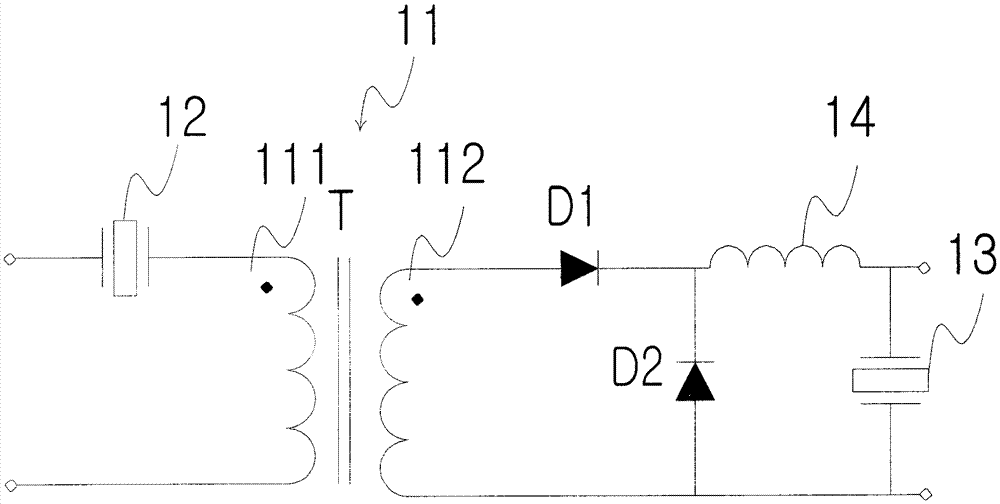
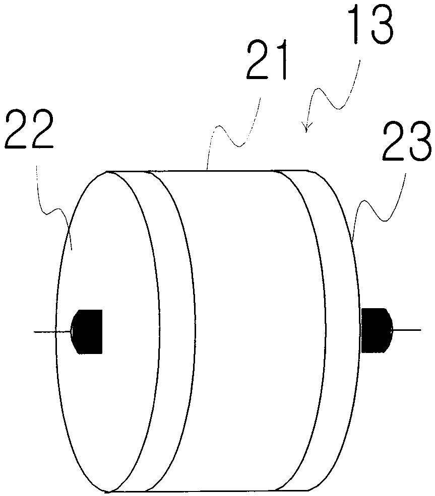
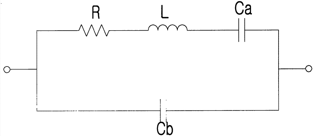
[0045] Please refer to the first figure, which is a schematic diagram of the first embodiment of the piezoelectric power converter applied to the half-bridge input of the present invention, which includes a transformer 11, at least one first piezoelectric component and at least one second piezoelectric component, Among them, the transformer 11 has a primary side 111 and a secondary side 112 . The primary side 111 of the transformer 11 is used as an inductance, and is connected in series with the first piezoelectric component to form a resonant circuit, and the first piezoelectric component is used as a piezoelectric oscillator 12 by utilizing its own capacitance characteristics, and is used for Replaces capacitors in traditional power converters. Among them, the piezoelectric vibrator 12 disclosed in this embodiment, as shown in the second figure A, is a disc-shaped substrate 21 made of piezoelectric material. Of course, its shape can also be square or rectangular or other geo...


PUM


Abstract

The invention discloses a piezoelectric power supply converter. A traditional capacitor is replaced by using a piezoelectric assembly. Because the piezoelectric assembly has higher capacitance than the traditional capacitor and can produce inverse voltage effect during power-on deformation and produce positive piezoelectric effect after the deformation to generate positive charges, the piezoelectric assembly has voltage amplification effect, achieves high-power output and can overcome the defects of low voltage, high leakage current and low power output of the traditional capacitor.

Description

【Technical field】 [0001] The present invention relates to a piezoelectric power converter, in particular to a power converter that utilizes piezoelectric components to increase power output. 【Background technique】 [0002] Currently, more and more portable devices provide color screens, stereo audio, and advanced features such as connectivity, such as GPRS, wireless networking, and Bluetooth, as well as video and camera capture. Compared with bloated and bulky portable devices, consumers expect product design that is not only thin and light, easy to operate, but also has a long battery life. Consumer preferences have created a dilemma for circuit design engineers: they must provide more power to the system and generate more banks of voltage, but at the same time, the space and battery capacity available for power supplies in portable products But it is decreasing day by day. [0003] In order to meet these technical requirements, designers must use higher efficiency power ...

Claims


Application Information

Patent Timeline
Patent Type & Authority Patents(China)
IPC IPC(8): H02M7/04
Inventor 魏道金
Owner MIDAS WEI TRADING
Learn More