

Piezoelectric resonator structure
A piezoelectric resonator and piezoelectric layer technology, applied in the field of piezoelectric resonators, can solve the problems of amplification, inappropriateness, strong fluctuation of filter passband, etc., and achieve improved Q value, low passband insertion loss, and superior electrical Effects of Features
Active Publication Date: 2010-12-22
ROFS MICROSYST TIANJIN CO LTD
View PDF7 Cites 27 Cited by
- Summary
- Abstract
- Description
- Claims
- Application Information
AI Technical Summary
Problems solved by technology
This method requires a large Q at the same time s and value applications (such as UMTSband 1 duplexer) are not suitable
Furthermore, at frequencies below f s The strength of the spurious resonant mode of the filter is thus amplified, and the spurious resonant mode will cause strong fluctuations in the passband of the filter
Method used
View moreImage
Smart ImageViewing Examples

Examples
Embodiment Construction
Login to View More PUM
 Abstract
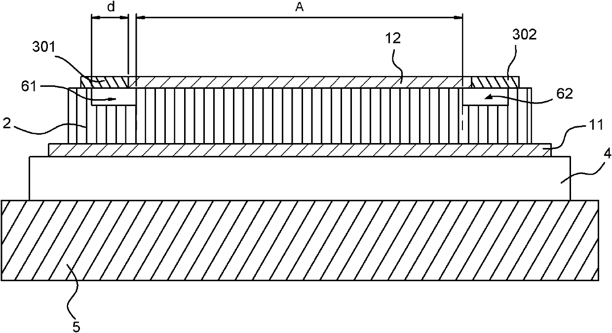
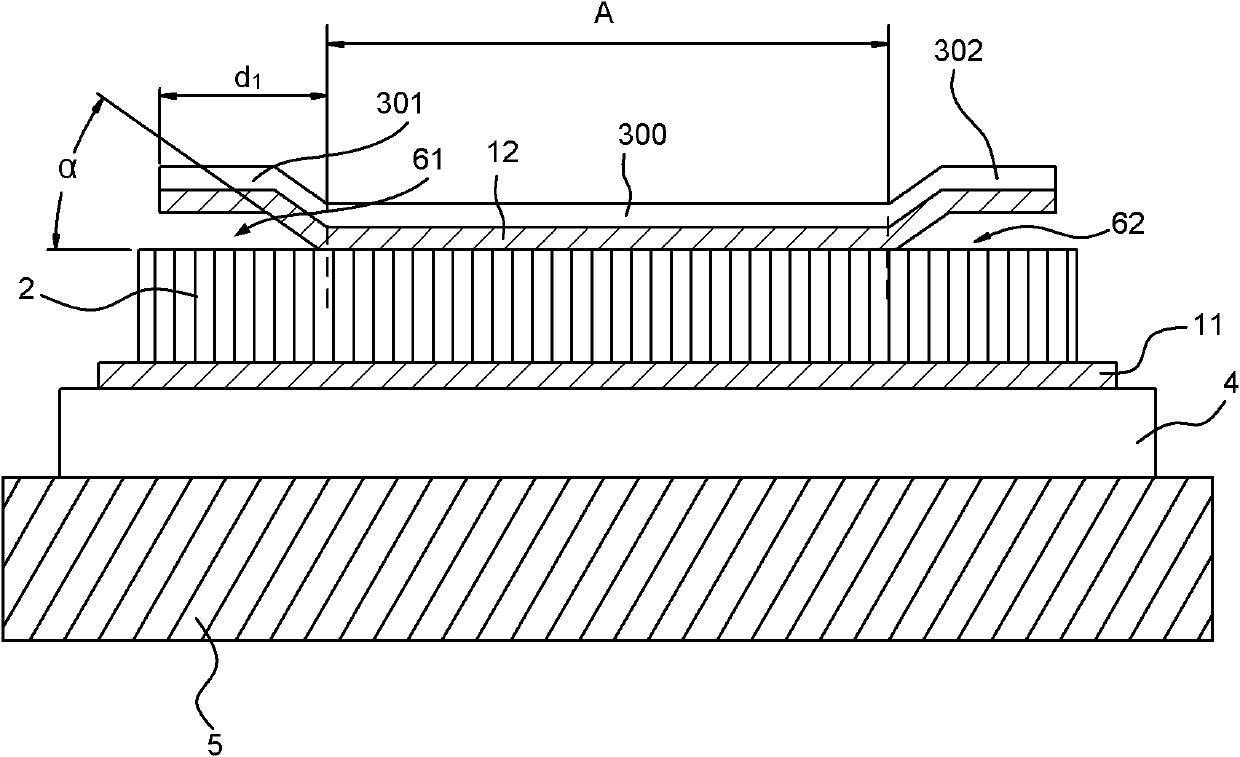
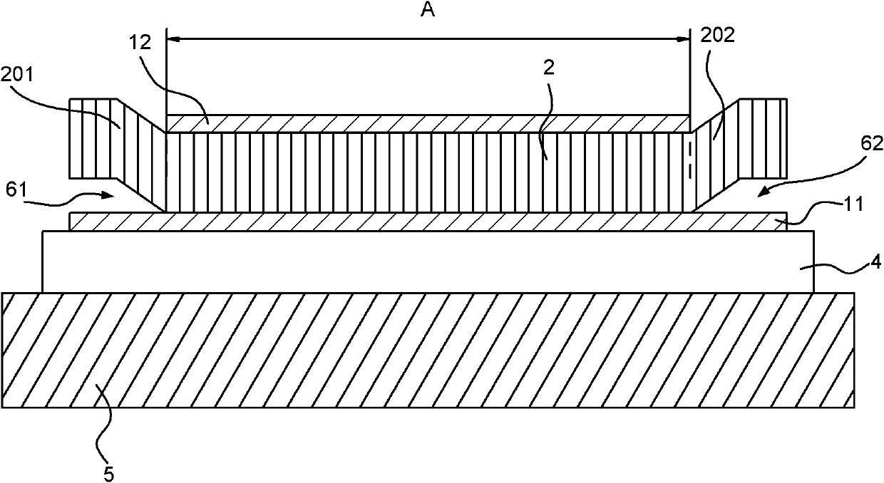
The invention discloses a piezoelectric resonator structure, which comprises a substrate, an acoustic reflection layer, a first electrode, a piezoelectric layer and a second electrode, which are provided with a top surface, a bottom surface, a first tail end, a second tail end and a middle part respectively; the substrate, the acoustic reflection layer, the first electrode, the piezoelectric layer and the second electrode are arranged in turn from the bottom to the top; and an overlapping region of the substrate, the acoustic reflection layer, the first electrode, the piezoelectric layer and the second electrode is defined as an effective excitation region. A series of air gaps and interference structures are formed at the first tail ends and the second tail ends of the piezoelectric layer and the second electrode to improve the electrical performance of a resonator. The piezoelectric resonator structure greatly improves the Q value of the resonator nearby a parallel resonance frequency, meanwhile does not affect the Q value and parasitic mode strength of the resonator nearby a series resonance frequency, and does not reduce the electromechanical coupling coefficient of the resonator. A filter adopting the resonator structure has more predominant electrical properties such as lower pass-band insertion loss and the like.
Description
technical field The present invention relates to a piezoelectric resonator. In particular, it relates to a piezoelectric resonator structure whose electrical characteristics can be improved. Background technique Piezoelectric bulk acoustic resonators used in radio frequency (RF) filters for wireless communication devices are generally classified into two types. One type is called a film bulk acoustic resonator (FBAR). A typical FBAR structure is composed of two metal electrode layers sandwiching a piezoelectric material layer. Both metal electrodes are in direct contact with the air so that the acoustic energy is contained within the piezoelectric resonator cavity. In the actual structural configuration, additional layers will be added to the metal electrodes to improve the performance of the FBAR such as physical strength, passivation and temperature compensation. Another type is called a solid-state mounted resonator (SMR). In SMRs, acoustically reflective layers cont...
Claims
Login to View More Application Information
Patent Timeline
 IPC IPC(8): H03H9/02
Inventor庞慰张浩
OwnerROFS MICROSYST TIANJIN CO LTD