Optical fiber Bragg grating refractive index sensor

A refractive index sensor and optical fiber Bragg technology, which is applied in the direction of phase influence characteristic measurement, etc., can solve the problems of affecting the application of the sensor, weakening the strength, increasing the cost, etc., and achieve the effect of simple structure, reducing influence and eliminating measurement error

Inactive Publication Date: 2010-12-29
SOUTH CHINA NORMAL UNIVERSITY
View PDF3 Cites 10 Cited by
  • Summary
  • Abstract
  • Description
  • Claims
  • Application Information

AI Technical Summary

Problems solved by technology

The disadvantage of this method is that because the cladding of the optical fiber is removed, the bearable

Method used


Image

  • Optical fiber Bragg grating refractive index sensor
  • Optical fiber Bragg grating refractive index sensor
  • Optical fiber Bragg grating refractive index sensor

Examples


Example Embodiment

[0050] Example 1:

[0051] In an example, the optical fiber sensor of the present invention is used to measure the reflection spectra of solutions with different refractive indexes, such as Figure 4 As shown, the curves a, b, c, and d in the figure correspond to the results of placing the optical fiber sensor head in air, pure water, 12% by mass sucrose solution and 24% by mass sucrose solution, respectively. From Figure 4 It can be seen that the side mode suppression ratio of the fiber Bragg grating increases with the increase of the refractive index of the solution placed in the fiber sensor head.

[0052] Table 1 shows the relationship between the side-mode suppression ratio of the fiber Bragg grating and the refractive index of the same liquid (sucrose solution) with different mass percentage concentrations.

[0053] Table 1

[0054] Concentration of sucrose solution (%)

[0055] in Figure 5 In, it is the data result and linear fitting curve of the refractive index measurem...

Example Embodiment

[0056] Example 2

[0057] In this example, the sensor of the present invention is used to measure the change of 15% by mass sucrose solution with temperature, such as Image 6 As shown, the temperature of the sucrose solution is 30 o C and 60 o From the sensor reflection spectrum of C, it can be seen that the Bragg wavelength of the fiber Bragg grating shifts to the long-wave direction with increasing temperature, and its side mode suppression ratio remains unchanged (the refractive index of the sucrose solution does not change significantly with temperature).

[0058] Table 2 shows the relationship between the Bragg wavelength of the fiber Bragg grating and the temperature.

[0059] Table 2

[0060] temperature / o C

[0061] in Figure 7 In, it is the data result and linear fitting curve of the temperature measurement of the same concentration of sucrose solution using the present invention. The solid line in the figure is the theoretical curve, and the small square point is the...


PUM


Abstract

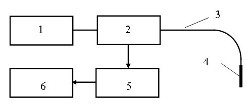
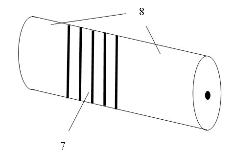
The invention discloses an optical fiber Bragg grating refractive index sensor which comprises a broadband light source (1), an optical fiber coupler (2), a transmission optical fiber (3), an optical fiber sensing head (4) and a spectrograph (5), wherein the broadband light source (1) is connected to an input end of the optical fiber coupler (2), one output end of the optical fiber coupler (2) is connected with the optical fiber sensing head (4) through the transmission optical fiber (3), and the other output end of the optical fiber coupler (2) is connected with the spectrograph (5); light reflected by the optical fiber sensing head (4) is transmitted to the spectrograph (5) through the optical fiber coupler (2), and the spectrograph (5) is communicated with a computer (6); and the optical fiber sensing head (4) is a common optical fiber Bragg grating with a tail fiber. The sensor can be used for measuring refractive indexes and simultaneously measuring the refractive indexes and temperature, and has the advantages of real-time online and remoter detection capability, large measurement range, high sensitivity, strong stability and convenient operation.

Description

technical field [0001] The invention relates to a refraction index sensor, in particular to a refraction index sensor of an optical fiber Bragg grating. Background technique [0002] Refractive index is a very important parameter in the fields of physics, biology, chemistry and other disciplines, and its accurate measurement is of great significance and application in chemical industry, medicine, food and other related industrial sectors. Therefore, many methods for measuring the refractive index have emerged. Traditional measurement methods include grazing incidence, diffraction grating, laser irradiation and CCD measurement, as well as broadband absorption spectroscopy, titration and fluorescence quenching, but most of these methods are limited to the visible light range and are all It is a sampling method and cannot be monitored in real time. Subsequently, some new technologies such as photoacoustics, SPR sensors, and Raman spectroscopy have emerged, but these methods a...

Claims


Application Information

Patent Timeline
IPC IPC(8): G01N21/41
Inventor 蒙红云黄旭光
Owner SOUTH CHINA NORMAL UNIVERSITY
Why Eureka
Try Eureka