Forwardly and reversely symmetrical P-type radial varying doping and similar table-board negative angle shaped junction terminal thyristor

A forward and reverse, junction terminal technology, applied in the direction of thyristors, electrical components, circuits, etc., can solve the problems of asymmetric forward and reverse blocking voltages of thyristors, loss of cathode area, reduction of current capacity, and large occupied area of ​​molding area. , to achieve the effect of high voltage sheet thickness ratio, reduced occupied area, and small loss of cathode surface

Inactive Publication Date: 2010-12-29
西安派瑞功率半导体变流技术股份有限公司
View PDF0 Cites 9 Cited by
  • Summary
  • Abstract
  • Description
  • Claims
  • Application Information

AI Technical Summary

Problems solved by technology

Its disadvantages are as follows: ①Asymmetric forward and reverse shapes cause asymmetric forward and reverse blocking voltages of thyristors
Its disadvantages are as follows: ①The higher concentration of P-type impurities partially submerges the low concentration region on the surface of the negative angle shape terminal region
Considering the need for space charge region broadening, the low concentration of P - The depth of type diffusion must be large enough, the manufacturing process takes a long time and introduces an additional short base area and anode surface P - additional slice thickness
② Occupies a large area and loses too much cathode area
The modeling area occupies a large area, and the loss of cathode area leads to a decrease in flow capacity

Method used


Image

  • Forwardly and reversely symmetrical P-type radial varying doping and similar table-board negative angle shaped junction terminal thyristor

Examples


Embodiment Construction

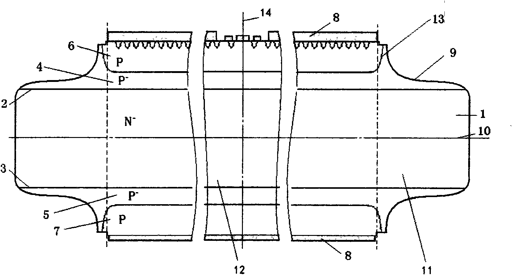
[0012] The present invention includes N - Type substrate (1), forward blocking junction (2), reverse blocking junction (3), forward and reverse blocking junctions (2, 3) are respectively provided with low concentration P - Type doped layers (4, 5) and higher concentration P-type doped layers (6, 7), which are divided into the general thyristor internal region (12) inside the metal ohmic contact layer (8) and the junction outside the metal ohmic contact layer (8). In the terminal region (11), the implementation mode of manufacturing positive and reverse symmetric P-type radial variable doping is: first, N - Type substrate (1) Two-sided symmetrical low-concentration P on both sides of the original single wafer - Type doping, the junction depth is 20-40μm shallower than the type II junction terminal structure, and the sheet resistance Rs is 500-1000Ω, forming a low-concentration P - Doped layer (4, s5), low concentration P - Type doped layer (4, 5) in N - The forward and reve...


PUM


Abstract

The invention relates to a forwardly and reversely symmetrical P-type radial varying doping and similar table-board negative angle shaped junction terminal thyristor. A higher concentration P-type doped layer forms a high-low junction which is a non-parallel plane junction on a low-concentration P-type doped layer; a junction surface bends to prevent higher concentration P-type impurities from entering junction terminal areas; and the edges of the forward and reverse junction terminal areas have similar table-board negative angle shapes. The forwardly and reversely symmetrical P-type radial varying doping has an effect of thinning P-area from double sides; and the forwardly and reversely symmetrical similar table-board negative angle shapes have effects of thinning a long base area, reducing occupied area per se, increasing cathode area and balancing forward and reverse voltage resistance. The forwardly and reversely symmetrical P-type radial varying doping and similar table-board negative angle shaped junction terminal thyristor has the characteristics of symmetrical forward and reverse block voltages, no additional thickness of long and short base areas and maximum cathode area. Compared with the thyristor made from an original silicon material with the same resistivity and diameter, the forwardly and reversely symmetrical P-type radial varying doping and similar table-board negative angle shaped junction terminal thyristor has the advantages of highest blocking voltage, highest ratio of breakover voltage to chip thickness and maximum cathode area.

Description

technical field [0001] The invention relates to the technical field of semiconductor power electronics, and is a forward and reverse symmetrical P-type radially variable doping and mesa-like negative-angle shaped junction terminal thyristor with special doping and shaped junction terminals. Background technique [0002] There are currently two types of UHV high-power bidirectional blocking silicon thyristor junction terminals known: 1. Forward P-type radial variable doping, mesa-like negative-angle shape, and reverse positive-angle shape (hereinafter referred to as I-type). Its disadvantages are as follows: ①The asymmetry of the forward and reverse shape causes the asymmetry of the forward and reverse blocking voltage of the thyristor. ② Positive angle molding will inevitably introduce an additional long base region (N region) to obtain a certain reverse blocking voltage to increase the thickness of the film. ③From the edge of the chip to the inside, the reverse positive an...

Claims


Application Information

Patent Timeline
Patent Type & Authority Applications(China)
IPC IPC(8): H01L29/74H01L29/06H01L29/36
Inventor 陆剑秋王正鸣
Owner 西安派瑞功率半导体变流技术股份有限公司
Why Eureka
Try Eureka