Filter assembly

A filter and component technology, applied in the field of filters, can solve the problems of large dielectric rods, difficult to handle, frequency tuning can only be performed in one direction, etc., to achieve the effect of multi-welding and waste cost reduction

Active Publication Date: 2010-12-29
TELEFON AB LM ERICSSON (PUBL)
View PDF6 Cites 16 Cited by
  • Summary
  • Abstract
  • Description
  • Claims
  • Application Information

AI Technical Summary

Problems solved by technology

The problem with existing solutions using soldering to attach the TM mode dielectric rod to the filter housing and / or cover is that once the dielectric rod is assembled and welded, the dielectric rod cannot be replaced
However, frequency tuning performed by material removal is irreversible, i.e., frequency tuning can only be done in one direction
This involves a great risk: removing too much material makes the dielectric rod and the entire ceramic filter less useful, quite possibly even useless
Second, there is a great risk of the dielectric rod being damaged
[0014] Another disadvantage of existing solutions for grounding dielectric rods by soldering is that it is difficult to obtain a repeatable soldering process for a complete filter consisting of several dielectric rods when soldering directly to the filter housing and filter cover
This also has a negative impact on the long-term reliability of the welded joint
When heating the entire filter assembly, it is also required that all components inside the product can withstand the soldering temperature; this will limit the choice of materials, such as plastics, and may also increase the cost of materials
High-quality products are difficult to handle after soldering operations due to the latent heat in the filter housing, filter cover and ceramic, so the cooling process must be long, which increases production lead time and costs
In addition, multiple weld seam directions, such as two directions in the case of TM single-mode filters or four directions in the case of TM dual-mode filters, complicate the welding process
In addition, tight mechanical tolerances are necessary when soldering directly to the filter housing and cover, which is also costly

Method used


Image

  • Filter assembly
  • Filter assembly
  • Filter assembly

Examples


Embodiment Construction

[0032]The invention is limited to filter assemblies that may be practiced in the embodiments described in detail below.

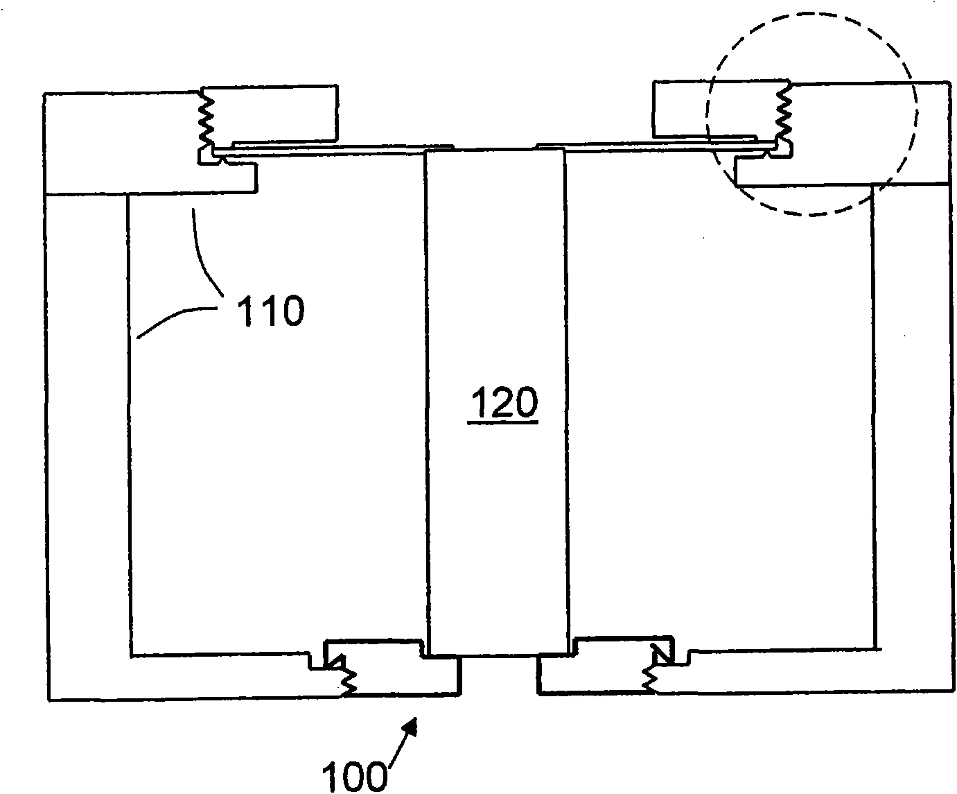
[0033] figure 1 A cross-section of a filter assembly 100 according to an embodiment of the invention is shown. The filter assembly 100 includes a filter base 110 and at least one dielectric rod 120 . The filter assembly 100 according to this solution may comprise a plurality of dielectric rods 120, for example thirty. then in figure 1 Only one dielectric rod 120 is depicted in . Filter assembly 100 may be a TM single mode resonator.

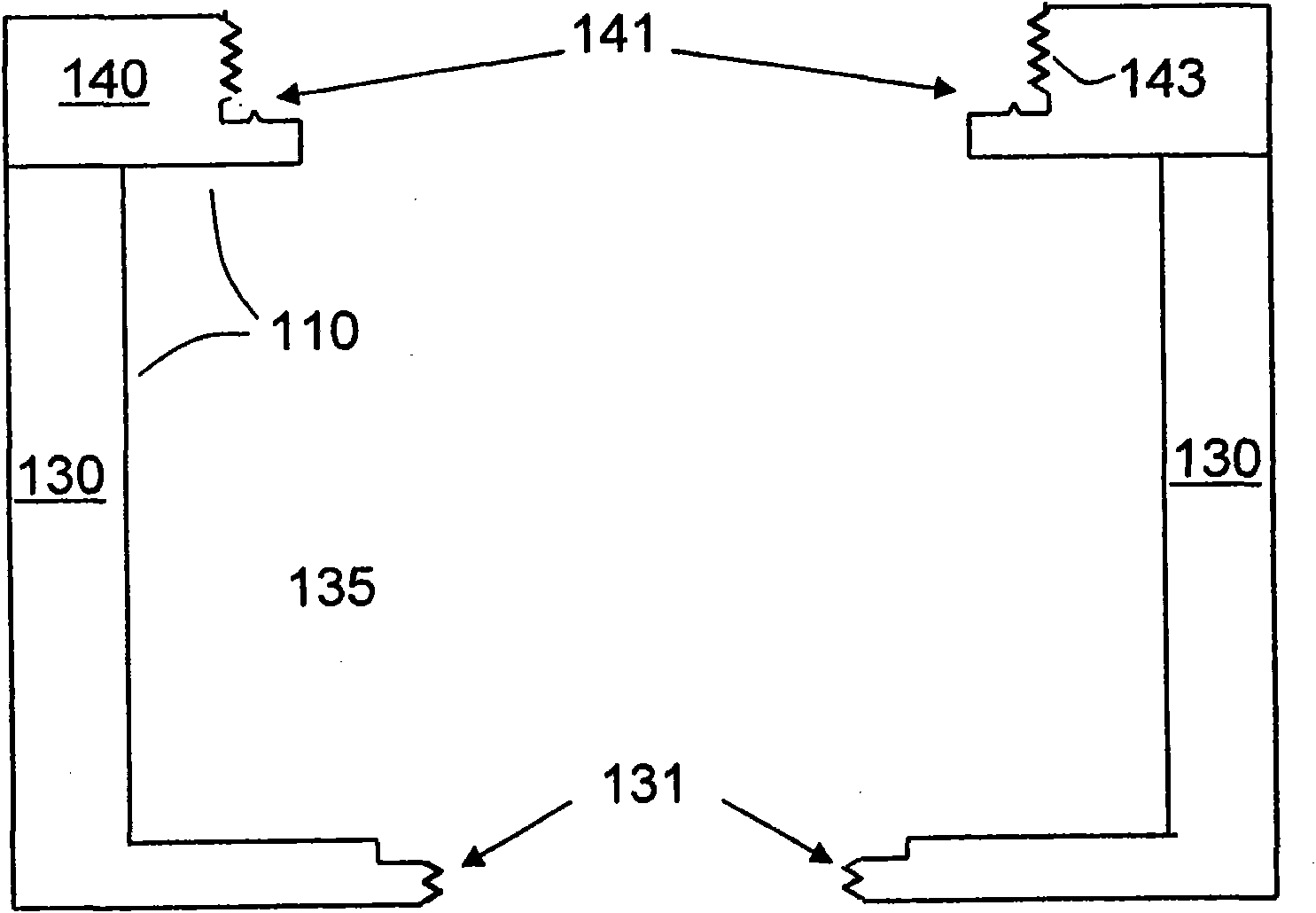
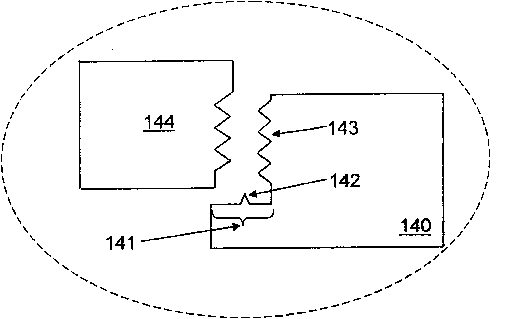
[0034] figure 2 A cross-section of the filter chassis 110 is depicted. The filter chassis 110 may include a filter housing 130 , a filter cavity 135 , and a filter cover 140 . Examples of filter housing 140 may be, for example, a cover, cap, or cover. The filter housing 130 may be adapted to be provided with a filter housing 140 . The filter housing 130 and the filter housing 140 may be made of silver-plated copper o...


PUM


Abstract

An object of the present invention is to provide an improved and simplified filter assembly. The object is achieved by a dielectric rod (120, 610, 620) for a filter chassis (110). The dielectric rod (120, 610, 620) extends between a first end (121) and a second end (122). The dielectric rod (120, 610, 620) comprises a conductive element (150) placed at the first (end 121). The conductive element (150) is adapted to be in conductive contact with a first contact means (141) of the filter chassis (110). The dielectric rod further comprises a second fastening element (160) placed at the second end (122). The second fastening element (160) is adapted to be attached and detached to a first fastening element (131) comprised in the filter chassis (110), such that the dielectric rod (120, 610, 620) is replaceable in the filter chassis (110).

Description

technical field [0001] The invention relates to the field of filters. More particularly, the present invention relates to a dielectric rod, a filter chassis, a filter assembly and a radio transmission device including such a filter assembly. Background technique [0002] Filters are circuits that can be used in communication systems to compensate for disturbances such as interference caused by the transmission medium itself between the transmitter and receiver. The filter removes unwanted communication signal components and / or enhances wanted communication signal components. [0003] Radio frequency (RF) filters and microwave filters represent a class of filters designed to operate on signals in the megahertz to gigahertz frequency range. This frequency range is the range used by most broadcast radios, televisions and wireless communication systems such as cellular communication systems, Wi-Fi, WiMax, LTE and the like. Accordingly, most wireless communication devices will...

Claims


Application Information

Patent Timeline
Patent Type & Authority Applications(China)
IPC IPC(8): H01P7/10H01P1/208H01P1/20H01P11/00
CPCH01P1/2084H01P7/10
Inventor 伊萨·马利万尼奥班尼·格斯塔福森
Owner TELEFON AB LM ERICSSON (PUBL)
Why Eureka
Try Eureka