Double-rotor disc self-excited retarder and control method thereof

A retarder, double rotor technology, applied in asynchronous inductive clutch/brake, electric braking system, electric vehicle and other directions, can solve the problems of high power consumption, loudspeaker whistling, increase and other problems, to achieve easy maintenance, The effect of simple circuit structure and simple system structure

Inactive Publication Date: 2011-01-05
JIANGSU UNIV
View PDF4 Cites 31 Cited by
  • Summary
  • Abstract
  • Description
  • Claims
  • Application Information

AI Technical Summary

Problems solved by technology

However, the negative impact of installing these eddy current retarders on the vehicle is also obvious. On the one hand, the eddy current retarder needs to consume a lot of electric energy when it works (the total excitation current is generally above 100A at the highest gear), which brings additional energy consumption
On the other hand, the huge current required for the operation of the eddy current retarder will have an impact on other on-board electrical equipment
After the passenger car is equipped with an eddy current retarder, the load on the generator and battery is increased, and the vehicle power supply circuit must be adjusted accordingly; in the case of improper power configuration or circuit design connection of the power supply equipment, the voltage of the electric system of the passenger car is slowed down by the eddy current retarder. When the device is working, there will be a sharp drop, causing

Method used


Image

  • Double-rotor disc self-excited retarder and control method thereof
  • Double-rotor disc self-excited retarder and control method thereof
  • Double-rotor disc self-excited retarder and control method thereof

Examples


Embodiment Construction

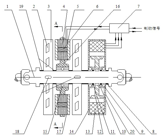
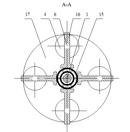
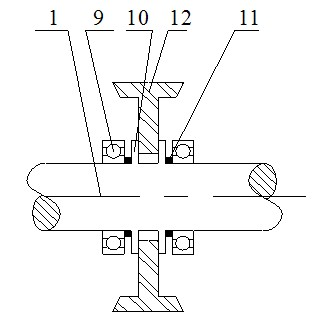
[0015] Such as Figure 1-2 , the present invention comprises automobile transmission shaft 1, retarder 17 and power generation device 20, and retarder 17 is fixedly installed on automobile transmission shaft 1, and automobile transmission shaft 1 is a stepped shaft, and also fixedly installs power generation device on automobile transmission shaft 1 20 and two rotor disks 3, the two rotor disks 3 are respectively arranged on both sides of the retarder 17, this double rotor disk form can increase the braking torque. A centrifugal air duct 2 is processed inside the rotor disk 3 to facilitate heat dissipation. The rotor disk 3 is connected with the automobile transmission shaft 1 through the key 18, and when the automobile transmission shaft 1 rotates, the rotor disk 3 is driven to rotate through the key 18. A plurality of rotor disc thrust washers 19 are fixed on the automobile transmission shaft 1, and these plurality of rotor disc thrust washers 19 are respectively located be...


PUM


Abstract

The invention discloses a double-rotor disc self-excited retarder and a control method thereof. The retarder, a generating set and two rotor discs are fixedly arranged on a transmission shaft of an automobile, wherein the two rotor discs are arranged on both sides of the retarder; the retarder comprises a retarder coil, a retarder coil iron core and a retarder bracket; the generating set comprises a permanent magnet, a generating set stator coil and a generating set shell; a control unit comprises an amplifying circuit, a voltage transformation rectifier and two relays; the transmission shaft of the automobile rotates to drive the permanent magnet to rotate; a three-phase alternating voltage generated by the generating set stator coil is input into the voltage transformation rectifier; a brake signal is input into the amplifying circuit, so that a normally open contact of a first relay is closed; the current of a storage battery is input into a second relay through the normally open contact of the first relay; the second relay switches on the retarder coil; and an electromagnetic braking torque generated by the rotor disc prevents the transmission shaft of the automobile from rotating. The retarder has the advantages of power generating and retarding functions, high system radiating performance and higher braking efficiency and chassis space utilization ratio.

Description

technical field [0001] The invention relates to an electric eddy current retarder for automobiles, in particular to a double-rotor disc self-excited retarder therein. Background technique [0002] The eddy current retarder occupies the largest proportion in my country's automobile retarder industry due to its simple structure, low manufacturing cost, short response time, easy intelligent control of braking torque, low failure rate, and convenient maintenance. The use of the eddy current retarder improves the braking stability, driving safety and ride comfort of the car. At present, the commonly used eddy current retarders are: 1. Squirrel cage self-excited retarder, whose power generation device is a squirrel cage generator; 2. Drum type self-excited retarder, based on the eddy current retarder 3. A retarder with an independent power supply, the main shaft of the power generation device and the transmission shaft of the vehicle are connected by belts or gears. However, the...

Claims


Application Information

Patent Timeline
IPC IPC(8): B60L7/28H02K49/04
CPCY02T10/7241Y02T10/641Y02T10/64Y02T10/72
Inventor 何仁杨效军
Owner JIANGSU UNIV
Why Eureka
Try Eureka