Cavern arch mould spraying concrete construction structure and process

A technology of sprayed concrete and concrete, which is applied to structural elements, building components, underground chambers, etc., can solve the problems of high construction cost, safety and quality improvement, and long construction period, and achieve short construction period, guaranteed quality, and structural integrity. The effect of short construction period

Active Publication Date: 2011-01-05
SINOHYDRO BUREAU 7 CO LTD
View PDF5 Cites 16 Cited by
  • Summary
  • Abstract
  • Description
  • Claims
  • Application Information

AI Technical Summary

Problems solved by technology

[0003] According to the deficiencies of the prior art, the present invention discloses a construction structure and construction technology of the formwork sprayed concrete for the top arch of the cavern. Quality needs to be improved urgently

Method used


Image

  • Cavern arch mould spraying concrete construction structure and process
  • Cavern arch mould spraying concrete construction structure and process
  • Cavern arch mould spraying concrete construction structure and process

Examples


Embodiment 1

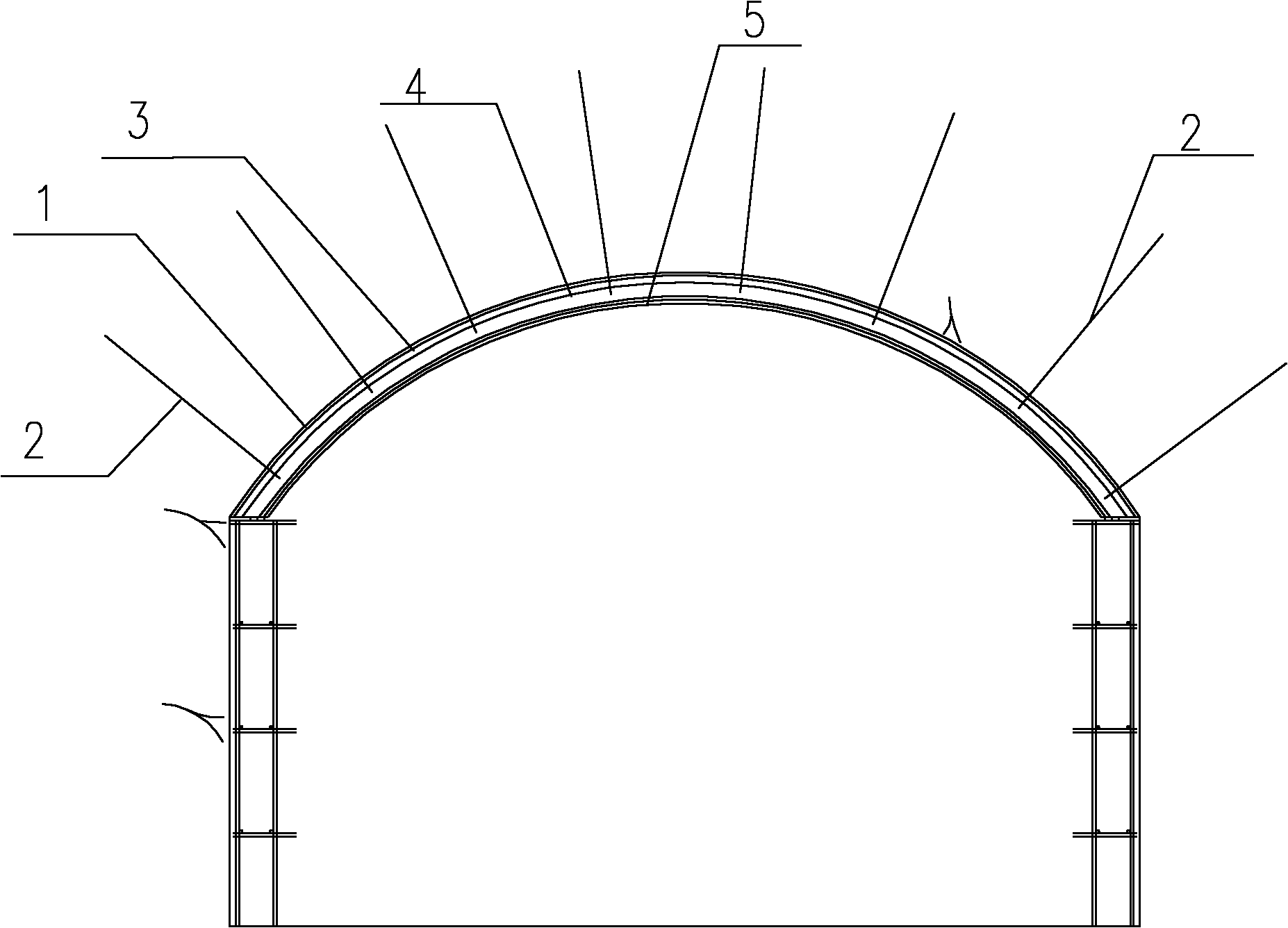
[0138] combine Figure 1 to Figure 3 .

[0139] figure 1 It is a schematic diagram of the sprayed concrete structure of the cave roof arch form of the present invention. The cavern top arch anchor rod 2 and steel structure are schematically shown in the figure, the present invention adopts formwork suspension technology, the weight of steel structure and formwork suspension structure utilizes anchor rod 2 to support in the concrete construction process, the quantity of anchor rod 2 and the drilling depth According to on-site design needs, this is a conventional mechanical calculation design, no matter how many anchor rods 2 and how to fix them all belong to the protection scope of the present invention. The steel structure is a necessary structural feature of concrete pouring. The steel structure in the concrete structure is to strengthen the toughness of the overall concrete structure and increase the tensile strength. No matter what concrete and steel structure is used, it...

Embodiment 2

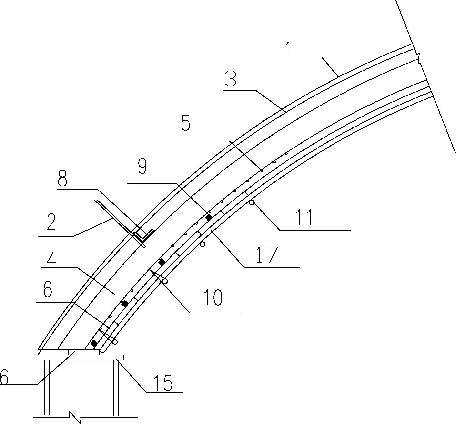
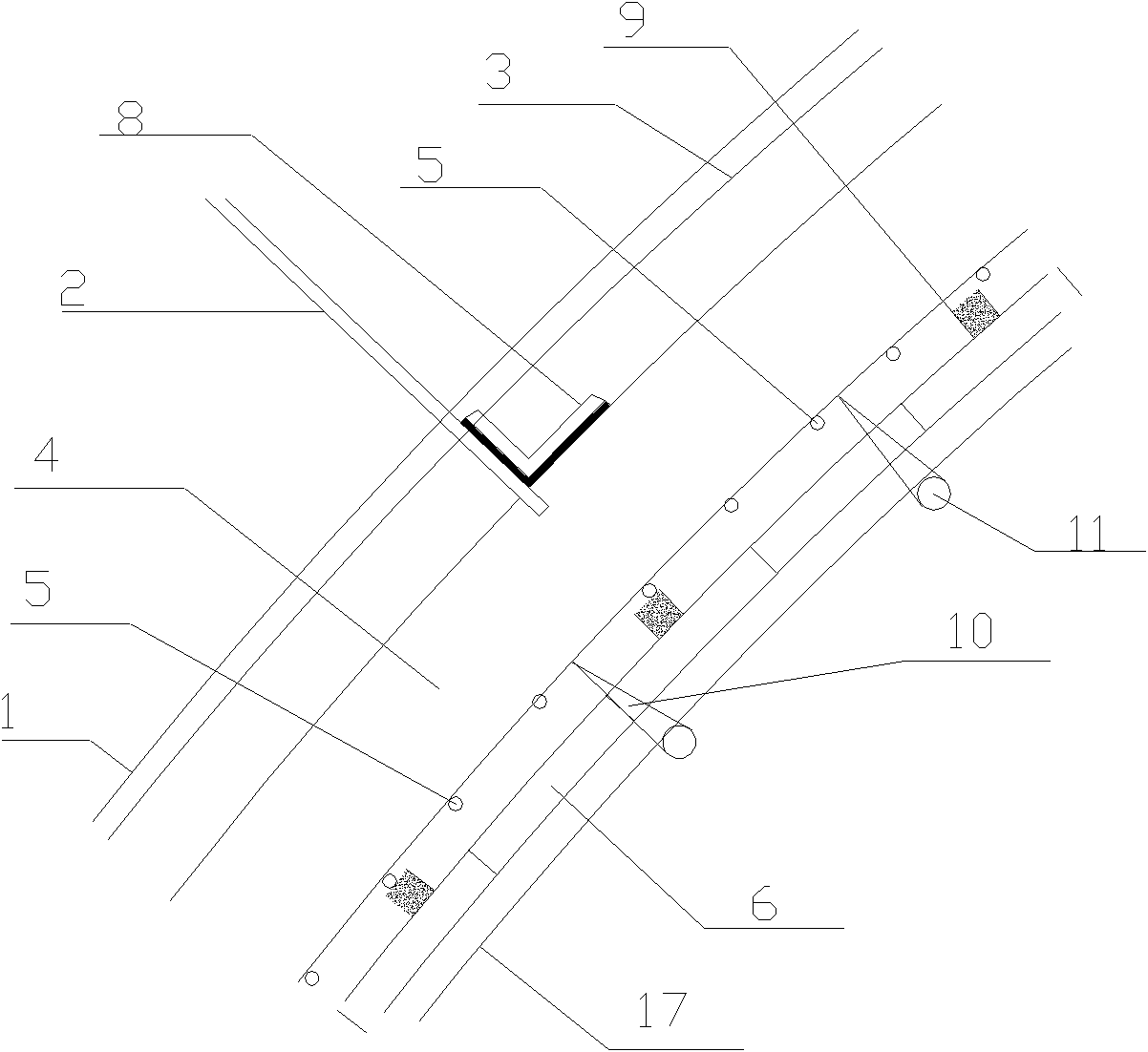
[0146] combine Figure 1 to Figure 4 , Figure 4 It is a schematic diagram of the construction state of the sprayed concrete in this example.

[0147] Adopt the specific structure of this example to carry out construction through the following steps:

[0148] A. Treatment of the bedrock surface. After excavation, carry out underexcavation treatment on the rock surface 1 and removal of loose rock blocks; underexcavation treatment ensures that the size of the building structure meets the design requirements and ensures the stability of the structure.

[0149] B, anchor rod construction, set up construction platform 13, carry out anchor rod 2 drilling and pouring; Carry out anchor rod construction after excavation, increase tendons and bones in rock mass, strengthen the intensity of anchorage area surrounding rock;

[0150] C. Install the inner layer of steel mesh, weld the supporting steel bars of the inner layer of steel mesh through the anchor rod 2, and then bind and instal...


PUM

PropertyMeasurementUnit
q valueaaaaaaaaaa

Abstract

The invention discloses a cavern arch mould spraying concrete construction structure and a cavern arch mould spraying concrete construction process. The structure comprises an anchor rod, a steel structure, concrete and a template, wherein the anchor rod is fixed in a bed rock; the steel structure is fixed through the anchor rod; the detachable template is suspended and fixed and forms a cavern arch pouring space with the bed rock together; and the concrete is sprayed into the pouring space through the template. The construction process comprises the following steps of: rock bed surface treatment, anchor rod construction, inner steel fabric installation, I iron installation, outer steel fabric installation, template installation, concrete spraying and the like. The construction needs no concrete delivery pump, does not need to build a full bearing scaffold and needs only a few constructors and spraying equipment. Therefore, construction materials are greatly saved; the construction period is short; arch lining concrete can be substituted by the mould spraying concrete of an underground cavern permanent structure; and the arch mould spraying concrete is more convenient to operate and the quality is assured.

Description

technical field [0001] The invention belongs to the technical field of construction engineering concrete construction, in particular to the technical field of water conservancy and hydropower engineering concrete construction, and in particular to a construction structure and construction technology of sprayed concrete for the top arch form of a cavern. Background technique [0002] Concrete construction is frequently used in construction projects. Conventional concrete construction can realize concrete pouring by mixing and vibrating. Concrete lining is traditionally used as the permanent structure of the top arch of underground caverns in water conservancy and hydropower projects. The advantage of using traditional top arch concrete lining is that the construction technology is mature. Conveying pumps and concrete construction personnel, and after the concrete lining of the top arch is completed, these materials, mechanical equipment and construction personnel will be idl...

Claims


Application Information

Patent Timeline
Patent Type & Authority Applications(China)
IPC IPC(8): E21D11/10E04C5/01E04C5/04
Inventor 张登柱伍有刚陈建国罗宁王先平
Owner SINOHYDRO BUREAU 7 CO LTD
Why Eureka
Try Eureka