Infrared imaging temperature measurement-type energy-flux density measuring device

A technology of infrared imaging and energy flow density, applied in the field of optoelectronics, to achieve fast measurement, ensure safety, and high precision

Inactive Publication Date: 2011-01-05
CHANGCHUN INST OF OPTICS FINE MECHANICS & PHYSICS CHINESE ACAD OF SCI
View PDF3 Cites 10 Cited by
  • Summary
  • Abstract
  • Description
  • Claims
  • Application Information

AI Technical Summary

Problems solved by technology

The invention is an energy flow density measuring device that is easy to use and can measure the energy flow distribution of light spots in various temperature ranges, which solves the problem of measuring the energy flow density of light spots in th

Method used


Image

  • Infrared imaging temperature measurement-type energy-flux density measuring device
  • Infrared imaging temperature measurement-type energy-flux density measuring device
  • Infrared imaging temperature measurement-type energy-flux density measuring device

Examples


Embodiment Construction

[0030] The working process of the present invention will be further described below in conjunction with accompanying drawings and examples.

[0031]In this example, the uncooled long-wave infrared imaging detector, the core device, is selected first, with a resolution of 320×240 pixels, a detector array size of 12.16mm×9.12mm, and a working band of 8-12 μm.

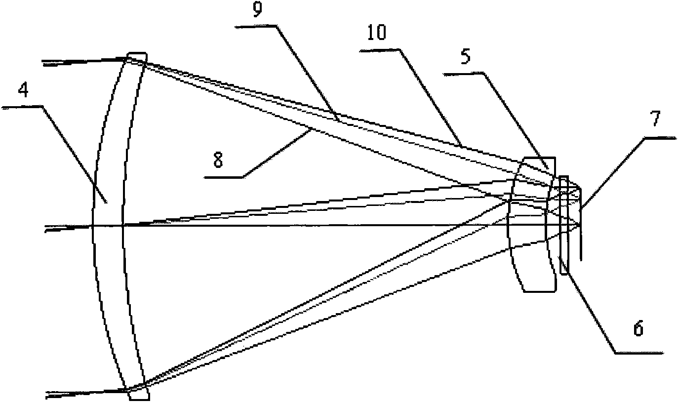
[0032] Design an infrared optical system with a field of view of 9°, a focal length of 90mm, and a relative aperture of 1:1. The structure diagram is attached figure 2 As shown, the optical material is germanium.

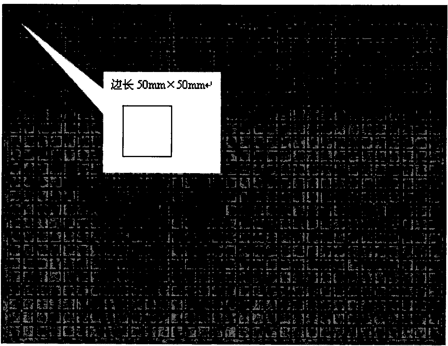
[0033] According to the calculation of the system structure parameter relationship described in the content of the invention, the optical system can measure a rectangular receiving screen with a side length of 11.5m×15.4m at 115m. The receiving screen is designed to be spliced ​​by 50mm×50mm square high-temperature resistant ceramic units. The receiving screen The back is made of heat insulating material, and...


PUM


Abstract

The invention discloses an infrared imaging temperature measurement-type energy-flux density measuring device, and belongs to infrared test equipment in the technical field of photoelectronics. The device consists of a high temperature-resistant light-gathering spot receiving screen 1, an infrared imaging system 2 and a data processing system 3. The spot receiving screen 1 is arranged at the position of a spot; the spectral characteristics of the infrared imaging system 2 and the receiving screen are calibrated by a standard light source; the thermal characteristics of the receiving screen is calibrated in a laboratory in advance; and all calibrated data are stored in software database of the data processing system 3. Temperature distribution of a light-gathering spot can be measured and energy-flux density distribution can be calculated by the data processing system 3. High-temperature light-gathering spot energy-flux density distribution can be measured in real time or the light-gathering spot energy-flux density distribution of a certain experiment can be measured offline. The device has the advantages of guarantee of instrument and operator safety, high measurement speed, high precision, flexible adjustment of receiving screen size, and no blind area in spot energy-flux density measurement range.

Description

technical field [0001] The invention belongs to the field of optoelectronic technology, and relates to an energy flow density distribution measuring device using the principle of infrared imaging temperature measurement, in particular to an infrared imaging temperature measurement type solar concentrated light spot energy flow distribution measuring device. Background technique [0002] Tower-type solar thermal power station is a large-scale solar energy utilization technology that has been commercially operated. The tower solar thermal power generation system consists of a concentrating mirror field, a tower, a heat absorber, a heat transfer medium, a heat storage device and a heat-to-electricity conversion device. The concentrating mirror field is composed of a large number of heliostats. Each heliostat rotates around two axes to converge sunlight to the heat absorber on the top of the tower. The heat absorber absorbs solar energy and converts it into heat energy of the he...

Claims


Application Information

Patent Timeline
IPC IPC(8): G01J1/00G01J1/04G01J5/00
Inventor 许文斌卢振武
Owner CHANGCHUN INST OF OPTICS FINE MECHANICS & PHYSICS CHINESE ACAD OF SCI
Why Eureka
Try Eureka