
Photo-acoustic spectrum gas detecting system based on distributed feedback optical fiber laser

A fiber laser and distributed feedback technology, which is applied in the field of photoacoustic gas detection system, can solve the problems of limited detection technology, loss of detection equipment function, and influence on measurement accuracy.

Inactive Publication Date: 2011-01-05
SHANDONG UNIV
View PDF6 Cites 7 Cited by
  • Summary
  • Abstract
  • Description
  • Claims
  • Application Information

AI Technical Summary

Problems solved by technology

[0004] 2008, 28(34): p40~46. The authors are Yun Yuxin, Chen Weigen, Sun Caixin, Pan Chong, and the article titled "Photoacoustic Spectroscopy Detection Method of Methane Gas in Transformer Oil" proposed a A new type of trace gas detection technology based on the photoacoustic effect, which has the advantages of high sensitivity, good selectivity, and large dynamic detection range. However, this detection technology is limited by the measurement environment. When there is an external electromagnetic field, it will seriously affect the measurement accuracy. , and even the function of the detection device will be lost

Method used


Image

  • Photo-acoustic spectrum gas detecting system based on distributed feedback optical fiber laser
  • Photo-acoustic spectrum gas detecting system based on distributed feedback optical fiber laser
  • Photo-acoustic spectrum gas detecting system based on distributed feedback optical fiber laser

Examples


Embodiment

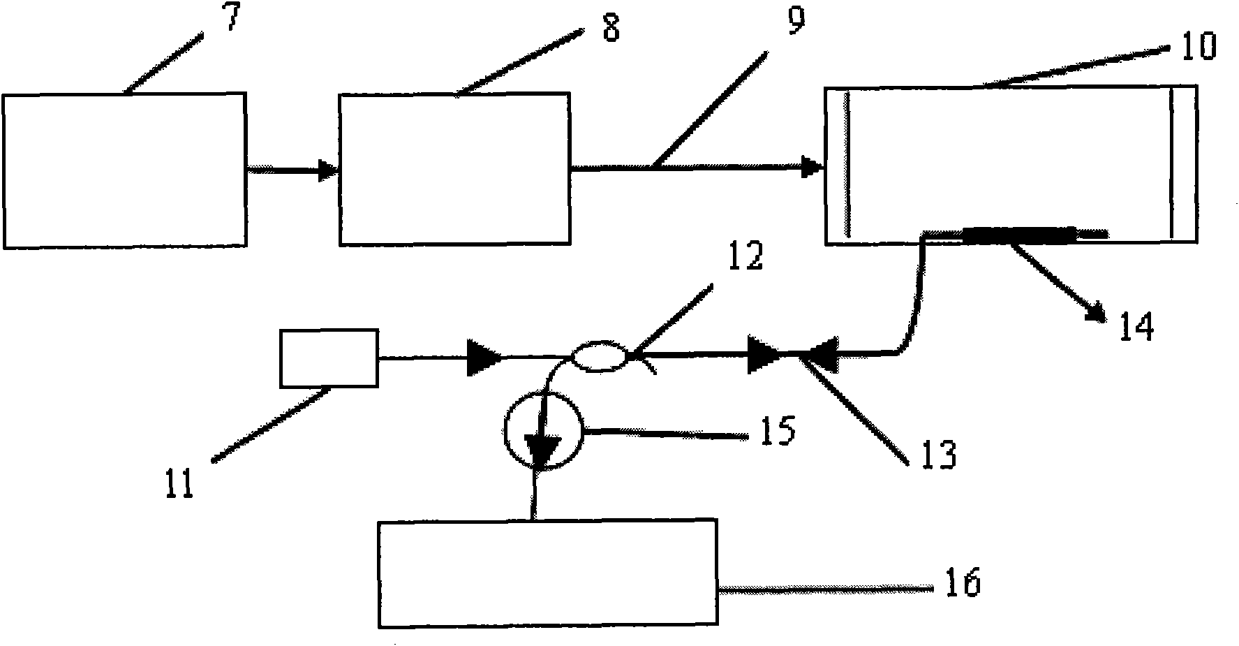
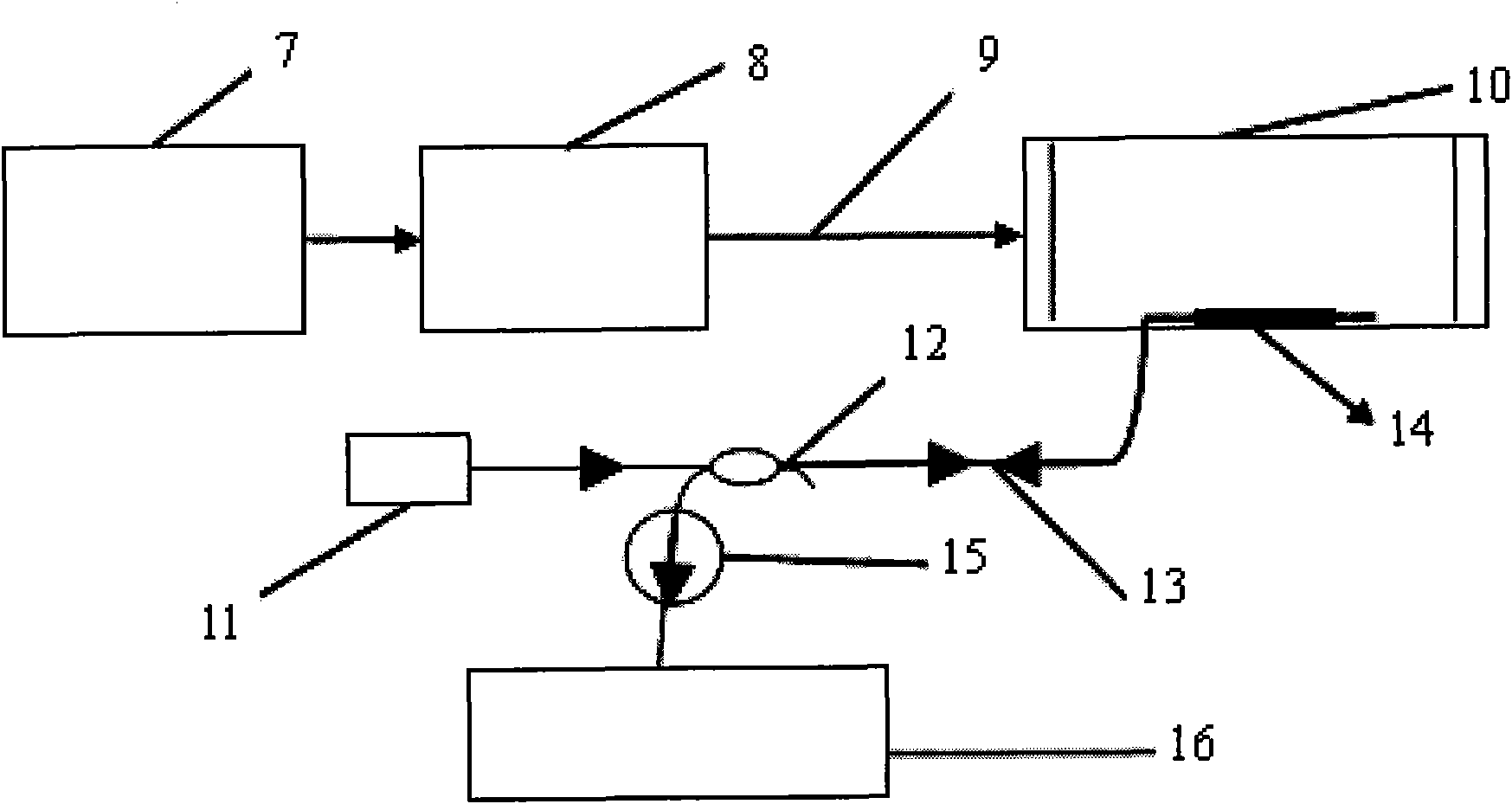
[0019] Examples of the present invention figure 2 As shown, it includes a coherent light source 7, a modulator 8, a photoacoustic cell 10, a 980 pump semiconductor laser (LD) 11, a wavelength division multiplexer (WDM) 12, a distributed feedback fiber laser (DFB-FL) 14, and an isolator (ISO) 15 and the wavelength demodulation system 16, the coherent light source 7 is connected with the modulator 8 through its own pigtail, and the modulator 8 is connected to the far-end photoacoustic pool 10 through a longer common optical fiber 9, and the light intensity period of the output The changing laser acts on the gas to be tested to generate a tiny sound, which constitutes the sound signal excitation optical path; the 980 pump semiconductor laser (LD) 11 is connected to the 980nm end of the wavelength division multiplexer (WDM) 12 through a pigtail and the subsequent optical path Form the detection optical path, it is characterized in that distributed feedback fiber laser (DFB-FL) 14...


PUM


Abstract

The invention discloses a photo-acoustic spectrum gas detecting system based on a distributed feedback optical fiber laser, belonging to the gas detection technologies. The photo-acoustic spectrum gas detecting system comprises a coherent light source, a distributed feedback optical fiber laser and the like, wherein the coherent light source is connected with a modulator through a self-supplied tail fiber, and the modulator is connected to a photoacoustic cell through a common optical fiber to form a sound signal excitation optical path; a 980 pump semiconductor laser is connected with a 980nm end of a wavelength division multiplexer through the tail fiber to form a detection optical path with a subsequent optical path. The invention is characterized in that the distributed feedback optical fiber laser is used as a sensor for probing sound and fixed in the photoacoustic cell, and one end thereof is connected to a common end of the wavelength division multiplexer through the common optical fiber; an 1550nm end of the wavelength division multiplexer is connected with an isolator; an output end of the isolator is connected with a wavelength demodulation system of the far end through the common optical fiber. The photo-acoustic spectrum gas detecting system can be normally used in the environment of strong electromagnet and radioactivity, can be used for detecting a special gas environment, and is convenient for forming a network by multiplexing a plurality of the systems so as to realize remote monitoring of multiple points.

Description

technical field [0001] The invention relates to an all-optical photoacoustic gas detection system based on a distributed feedback fiber laser (DFB-FL), specifically a system for photoacoustic gas detection using a distributed feedback fiber laser as an optical microphone. Background technique [0002] The photoacoustic effect is based on the effect that the material absorbs the modulated light and excites the sound wave through the non-radiative heat relaxation and heat release. As early as 1880, Bell et al. discovered the photoacoustic effect. Among many absorption spectroscopy methods for gas concentration detection, photoacoustic spectroscopy technology has the following advantages: wide testing range. Photoacoustic technology is to detect the light energy signal directly absorbed by the material through the non-radiative transition, instead of measuring the light energy signal transmitted through the sample, so that the reflection and scattering of the incident light by ...

Claims


Application Information

Patent Timeline
IPC IPC(8): G01N21/17G01N21/25
Inventor 常军宋复俊王伟杰孔德龙张燕王宗良公培军
Owner SHANDONG UNIV
Learn More