Vertical axis high-power wind driven generator with relatively high wind energy utilization rate

A wind turbine, vertical axis technology, applied to wind turbines, wind turbine components, wind turbines and other directions at right angles to the wind direction, can solve the problems of low wind energy utilization rate, large rotation radius, complex generator structure, etc. Achieve the effect of reducing production and operating costs, simple overall structure, and good application prospects

Active Publication Date: 2011-01-12
山东中能华源海上风电集团有限公司
View PDF8 Cites 0 Cited by
  • Summary
  • Abstract
  • Description
  • Claims
  • Application Information

AI Technical Summary

Problems solved by technology

Furthermore, horizontal-axis wind turbines need mechanisms such as yaw and propeller adjustment to solve the problem of windward resistance and control windward resistance, which makes the structure of the generator complex, takes up more parts and is prone to failure, affecting the utilization efficiency of wind turbines. Installation and maintenance costs also increase accordingly
In addition, due to the very large radius of rotation of the blade, the linear velocity at the tip of the blade is too high to generate resistance, and the wind energy has to do work to overcome this resistance, which makes the low utilization rate of wind energy even more compromised.

Method used


Image

  • Vertical axis high-power wind driven generator with relatively high wind energy utilization rate
  • Vertical axis high-power wind driven generator with relatively high wind energy utilization rate
  • Vertical axis high-power wind driven generator with relatively high wind energy utilization rate

Examples


Embodiment Construction

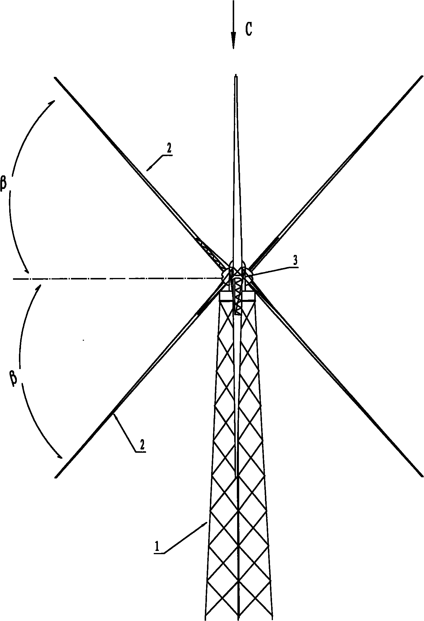
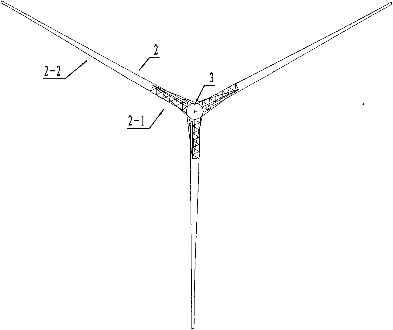
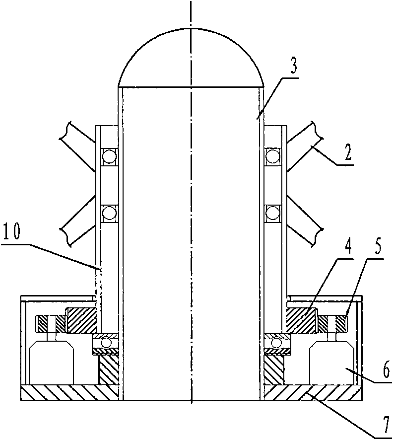
[0019] see figure 1 , figure 2 , the present invention is a vertical axis high-power wind power generator with a brand-new structure, which includes a tower 1, blades 2, a rotating mechanism, a generator, and a center column 3 fixed on the top of the tower. The axes are evenly distributed, and the blades form an acute angle β with the horizontal direction. The number of rows of blades and the degree of β angle can be selected according to factors such as fan power and material strength. The embodiment shown in the figure shows two rows of blades up and down, with three blades in each row, and the angle β between each blade and the horizontal direction is 45°.

[0020] see figure 1 and Figure 4-6 , the present invention improves and optimizes the sectional shape and installation angle of the blade 2 on the basis of the NACA0018 airfoil. The blade adopts a skin-covered truss structure, and the blade sectional shape refers to the cross-sectional shape of the skin. According...


PUM


Abstract

The invention discloses a vertical axis high-power wind driven generator with relatively high wind energy utilization rate, which is used for solving the problems of complex structure, high manufacturing cost and low wind energy utilization rate of horizontal axis wind driven generators. The vertical axis high-power wind driven generator comprises a tower, blades, a rotation mechanism, a generator and a centre column fixed on the top of the tower; after improved, the blades are uniformly distributed relative to the axe of the centre column; each blade forms an acute angle beta with the horizontal direction; the outline of the cross section of the blade is of a semi-closed curve with breach at the position close to the centre column and is of a closed symmetric curve at the position away from the centre column; and the centre plane of the blade deflects an angle alpha towards the breach direction by taking the blade mounting reference line as the axis, wherein the angle alpha is 5 to 15 degrees. The invention can increase the wind resistance and the wind resistance difference so that a fan can be normally started and operated even at relatively low wind speed; as yawing or variable pitch device is not needed, the entire structure of the fan is simple and compact and the manufacturing and operation cost is lowered, the energy consumption of the fan is reduced and the failure rate of the mechanical components is also reduced.

Description

technical field [0001] The invention relates to a power generation device, in particular to a vertical axis high-power wind power generator with low manufacturing and operating costs and high wind energy utilization rate, which belongs to the technical field of wind power generation. Background technique [0002] Among all kinds of green energy, wind energy is one of the renewable energy sources with great potential. At present, most of the wind power generators in operation in the world are horizontal axis wind power generators. Although this kind of generator is widely used, there are some structural problems, which are mainly reflected in the following aspects: First, the horizontal axis wind power generation The paddle wheel of the machine acts on the top of the support tower, making the support tower a cantilever beam structure. When using this structure to manufacture high-power fans, the tower height is generally 60 meters to 90 meters. In order to maintain the stabil...

Claims


Application Information

Patent Timeline
IPC IPC(8): F03D9/00F03D3/06F03D11/00F03D9/25F03D15/10
CPCY02E10/74Y02P70/50
Inventor 张远林
Owner 山东中能华源海上风电集团有限公司
Why Eureka
Try Eureka