Method for detecting large-caliber aspheric optical element by utilizing three-coordinate measuring machine

A three-coordinate measuring machine, spherical optics technology, applied in measuring devices, mechanical devices, mechanical measuring devices, etc., can solve the problems affecting the detection accuracy of optical components, long period, errors, etc., and achieve the effect of improving the three-coordinate detection accuracy

Inactive Publication Date: 2011-01-12
INST OF OPTICS & ELECTRONICS - CHINESE ACAD OF SCI
View PDF4 Cites 18 Cited by
  • Summary
  • Abstract
  • Description
  • Claims
  • Application Information

AI Technical Summary

Problems solved by technology

However, this method needs to use a standard plane mirror to realize surface shape detection by self-calibration method, or use a compensator that matches the aspheric surface to be tested to realize surface shape detection. Therefore, the disadvantages of the above detection method are: difficulty, high cost, long cycle
However, the probe of the three-coordinate measuring machine is not an ideal measuring point, but a probe with a certain radius, so the error caused by the radius of the probe will be brought during the measurement; at the same time, with the measurement stroke The increase will also introduce a certain stroke accumulation error
Therefore, the system error of the above-mentioned three-coordinate measuring machine will definitely affect the detection accuracy of optical components

Method used


Image

  • Method for detecting large-caliber aspheric optical element by utilizing three-coordinate measuring machine
  • Method for detecting large-caliber aspheric optical element by utilizing three-coordinate measuring machine
  • Method for detecting large-caliber aspheric optical element by utilizing three-coordinate measuring machine

Examples


Embodiment 1

[0024] Embodiment 1, detect caliber by the method of the present invention The process of aspheric mirror:

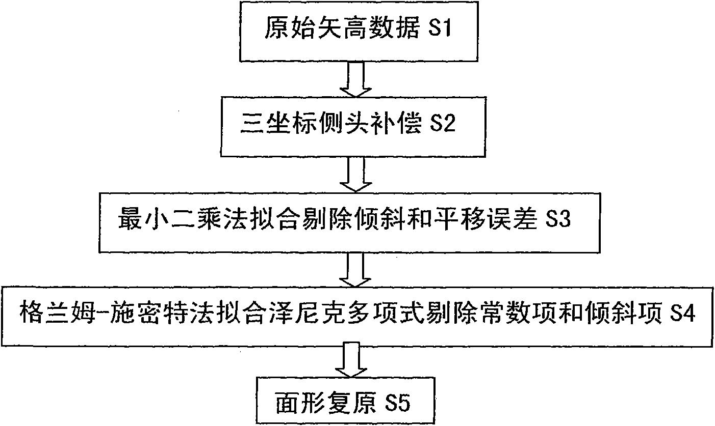
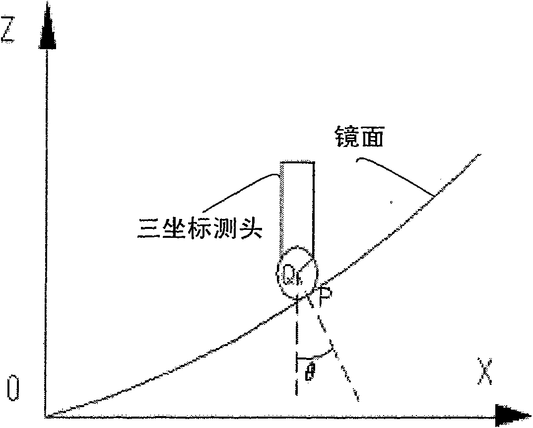
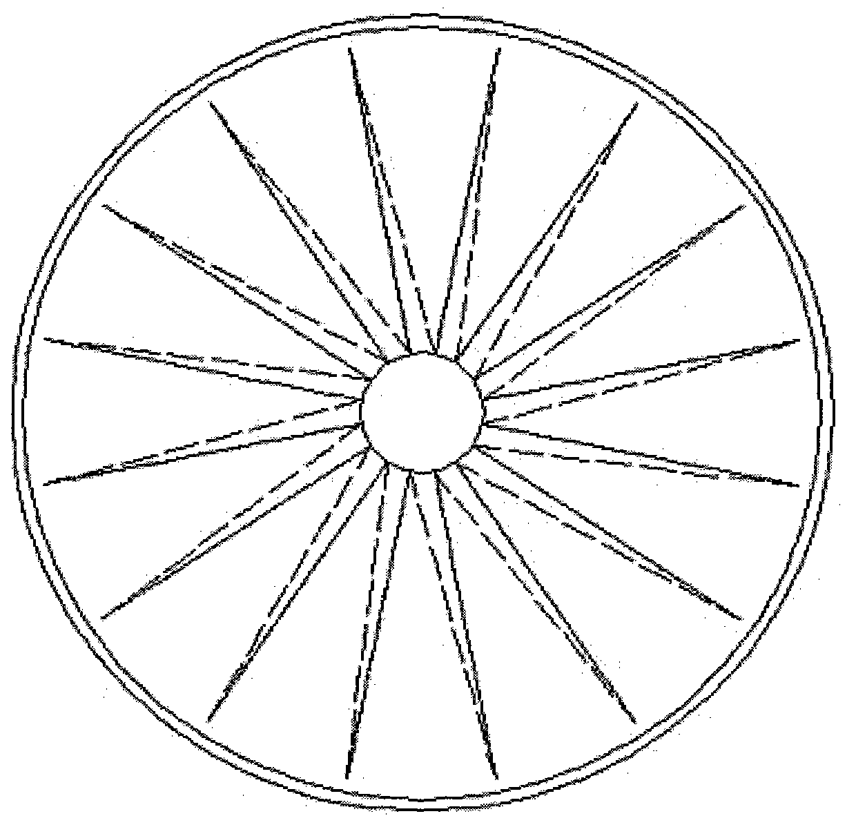
[0025] (1) if figure 1 The flow chart of data processing for detecting large-aperture aspheric optical elements with a three-coordinate measuring machine is shown, according to image 3 The measurement route shown measures 16×45 measurement points on the full aperture of the aspheric mirror, and obtains Figure 4 The surface height loss diagram shown, Figure 4 The middle abscissa is the diameter of the aspheric mirror, and the vertical coordinate is the height loss data of the aspheric mirror along the diameter direction. It can be seen that a total of 8 diameter lines and 16 radius lines have been measured, so there are a total of 16×45 measurement points in the full aperture, but this The detection graph is not intuitive, use the measurement point to draw the surface plan, such as Figure 5 It shows that the horizontal and vertical coordinates are the coordinate...


PUM


Abstract

The invention relates to a method for detecting a large-caliber aspheric optical element by utilizing a three-coordinate measuring machine, which comprises the following steps of: processing the data obtained by the three-coordinate measuring machine by utilizing an information processing technology, carrying out error compensation on the measuring head of the three-coordinate measuring machine by adopting a method for compensation by utilizing the measuring head, eliminating the tilting and translation errors of detected data by utilizing a least square method, eliminating the constant term and the tilting term after surface shape data Zernike polynomial fitting by a Gram-Schmidt orthogonalization method, and restoring the surface shape of the detected large-caliber aspheric optical element to realize the purpose of high-precision three-coordinate measurement of the large-caliber optical element. The invention comprehensively considers the error source of the three-coordinate measuring machine of the detected large-caliber aspheric optical element, so that the surface shape quality of the optical element can be more truly and objectively evaluated. The invention is used for processing the surface shape measurement error of the optical element by adopting the measuring-head compensation and least square methods and has important application value for the surface shape detection of the high-precision large-caliber optical element.

Description

technical field [0001] The invention belongs to the field of optical testing, and relates to an improvement on the surface error processing method of the large-diameter aspheric optical element, especially on the surface contact measurement error of the optical element. Background technique [0002] The manufacturing process of large aspheric optical components can generally be divided into workpiece forming, grinding, and polishing. Each processing stage has its corresponding surface shape detection method as a processing guide. The amount of material removed in the polishing stage is very small. At the same time, since the vertex curvature radius and eccentricity of the processed surface are basically not changed during polishing, the vertex curvature radius and eccentricity of the surface must be strictly controlled during the grinding stage. Therefore, the detection technology in the grinding stage is the key to the processing technology of large aspheric optical compone...

Claims


Application Information

Patent Timeline
Patent Type & Authority Applications(China)
IPC IPC(8): G01B5/008
Inventor 范斌伍凡曾志革周家斌景洪伟匡龙
Owner INST OF OPTICS & ELECTRONICS - CHINESE ACAD OF SCI
Why Eureka
Try Eureka