Method for judging and positioning bridge cable corrosion

A bridge cable and cable technology, applied in the field of non-destructive testing, can solve problems such as harsh conditions of use, poor ability to work at heights, hidden dangers of bridge safety, etc., to achieve the effects of reducing calculation errors, saving testing costs, and avoiding linear distortion

Active Publication Date: 2011-01-12
ZHEJIANG UNIV
View PDF4 Cites 22 Cited by
  • Summary
  • Abstract
  • Description
  • Claims
  • Application Information

AI Technical Summary

Problems solved by technology

[0002] Bridge cables are important structural parts for load-bearing and force transmission in bridges. During long-term use, they are constantly eroded by external environments such as temperature changes and strong winds, and the long-term repeated effects of vehicle loads and impacts as well as natural disasters. Corrosion or breakage of the steel wire will bring serious safety hazards to the bridge. Traditional non-destructive testing methods such as electromagnetic, ultrasonic flaw detection, machine vision or ray all require a cable climbing mechanism for scanning detection, which has complex mechanisms and the ability to work at heights. Poor, narrow scope of application, high failure rate, inconvenient to carry probes, harsh conditions of use, etc. Patent No. 200810196821.1 A magnetostrictive guided wave detection system for cable anchorage areas The detection of the cable, but there is no relevant method for the judgment of corrosion
He Cunfu and others used the dispersion compensation method to locate the acoustic emission, but the calculation of dispersion compensation is complicated and the accuracy is not high

Method used


Image

  • Method for judging and positioning bridge cable corrosion
  • Method for judging and positioning bridge cable corrosion
  • Method for judging and positioning bridge cable corrosion

Examples


Embodiment Construction

[0030] The present invention will be further described below in conjunction with accompanying drawings and examples.

[0031] This example includes the following specific steps:

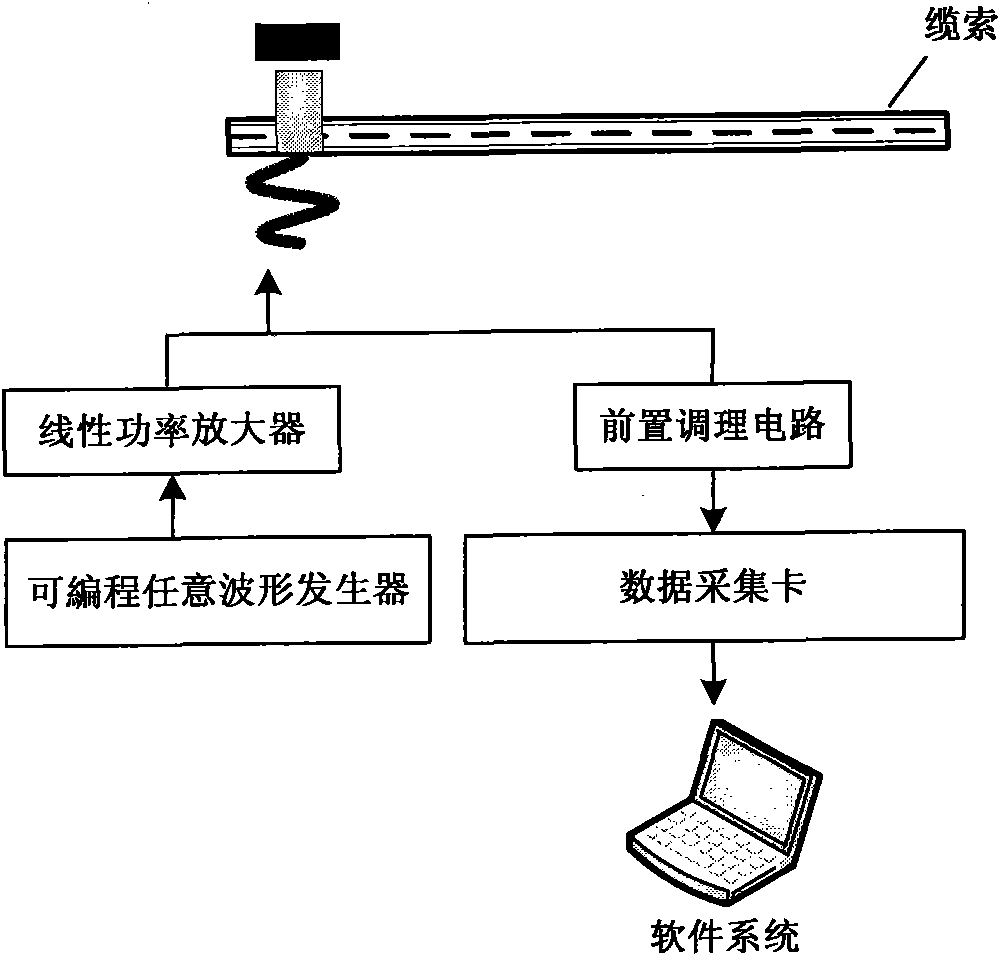
[0032] 1. If figure 1 As shown, a magnetostrictive sensor is installed on the cable to be tested. The sensor includes an excitation receiving coil and a permanent magnet bias magnetic field. The sensor is installed at one end of the cable to be tested;

[0033] 2. The programmable arbitrary waveform generator generates trigger group pulses, which are input to the sensor through the linear power amplifier, and the response signal is received on the same sensor. The card is read into the software system of the laptop;

[0034] 3. According to the geometric size, material characteristics and excitation signal conditions of the cable, a fine numerical model for cable corrosion judgment is established by using finite element technology, and a standard comparison signal is provided for the actual measure...


PUM


Abstract

The invention discloses a method for judging and positioning bridge cable corrosion. The method comprises the following steps of: arranging a sensor on a cable to be detected, acquiring an actual measured signal by using the sensor and reading the signal into a laptop by using a data acquisition card; establishing a fine numerical model for the cable corrosion judgment by adopting the finite element technology according to geometric dimension, material characteristics and excitation signal conditions of the cable, initializing the numerical model, analyzing and calculating to obtain a simulation response signal, and providing a standard comparison signal for the actual measured signal; using the actual measured signal as a judgment signal of the cable corrosion, and comparing the judgment signal and the standard comparison signal and analyzing the judgment signal by adopting a neural network analysis method, if the damage does not exceed a threshold value, judging that the cable is not corroded, otherwise alarming and positioning the corroded part; generating a recording report and recording a local database. The method for judging and positioning the bridge cable corrosion has the advantages of high resolution, high judging precision and no influence on normal use of the cable.

Description

technical field [0001] The invention relates to non-destructive testing technology, in particular to a method for judging and locating bridge cable corrosion. Background technique [0002] Bridge cables are important structural parts for load-bearing and force transmission in bridges. During long-term use, they are constantly eroded by external environments such as temperature changes and strong winds, and the long-term repeated effects of vehicle loads and impacts as well as natural disasters. Corrosion or breakage of the steel wire will bring serious safety hazards to the bridge. Traditional non-destructive testing methods such as electromagnetic, ultrasonic flaw detection, machine vision or ray all require a cable climbing mechanism for scanning detection, which has complex mechanisms and the ability to work at heights. Poor, narrow scope of application, high failure rate, inconvenient to carry probes, harsh conditions of use, etc. Patent No. 200810196821.1 A magnetostric...

Claims


Application Information

Patent Timeline
Patent Type & Authority Applications(China)
IPC IPC(8): G01N29/14G01N29/04
Inventor 项贻强吕福在竺冉王飞
Owner ZHEJIANG UNIV
Why Eureka
Try Eureka