Dual fluid nozzle atomizing and cooling closed system for high-power solid laser

A dual-fluid nozzle, solid-state laser technology, applied in lasers, laser parts, phonon exciters, etc., can solve the problems of complex system structure, inability to meet the low temperature requirements of the heat exchange surface, etc., and achieve the low heat exchange surface temperature requirements. , avoid dead zone, increase the effect of heat transfer capacity

Inactive Publication Date: 2011-01-12
TECHNICAL INST OF PHYSICS & CHEMISTRY - CHINESE ACAD OF SCI
View PDF0 Cites 19 Cited by
  • Summary
  • Abstract
  • Description
  • Claims
  • Application Information

AI Technical Summary

Problems solved by technology

The above system mainly has the following problems: (1) Under the influence of the boiling point of water under standard atmospheric pressure, the open cycle cannot meet the low temperature requirement of the heat exchange surface; (2) The open cycle needs to continuously replenish the circulating working fluid; (3) Two kinds of Working fluid, complex system structure

Method used


Image

  • Dual fluid nozzle atomizing and cooling closed system for high-power solid laser
  • Dual fluid nozzle atomizing and cooling closed system for high-power solid laser
  • Dual fluid nozzle atomizing and cooling closed system for high-power solid laser

Examples


Embodiment 1

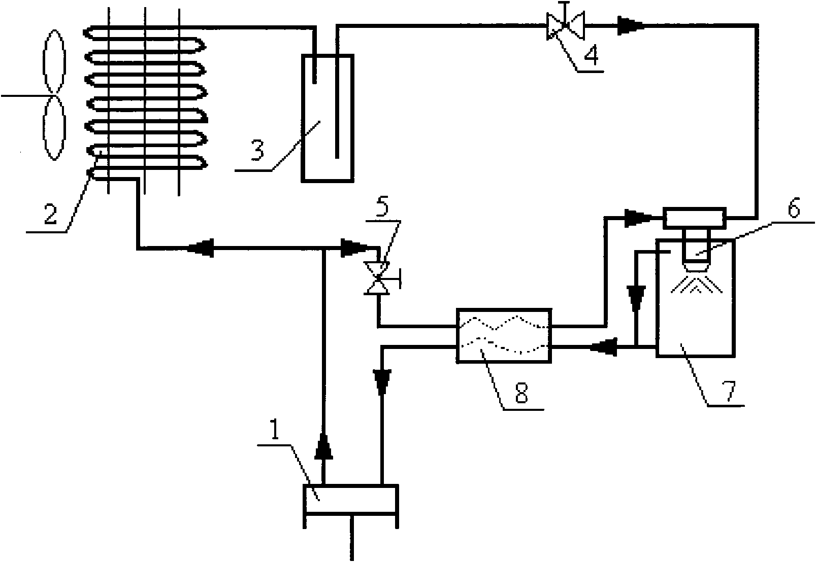
[0026] figure 2 The structural representation of an embodiment of the present invention that provides, its structure is:

[0027] An opening on the discharge pipe of the compressor 1 is connected to the gas phase inlet of the heat exchanger 8 via the second control valve 5; the gas phase outlet of the heat exchanger 8 is connected to the gas chamber of the two-fluid nozzle 6; The exhaust pipe of the compressor 1 is connected to the input end of the condenser 2; the output end of the condenser 2 is connected to the input end of the liquid receiver 3; the output end of the liquid receiver 3 is connected to the dual The liquid chamber of the fluid nozzle 6 is connected; the spray head of the two-fluid nozzle 6 extends into the heat sink 7; The inlet is connected; the superheated steam outlet of the heat exchanger 8 is connected with the suction pipe of the compressor 1 .

[0028] Its workflow is as follows:

[0029] Part of the high-pressure gas is introduced from an opening ...

Embodiment 2

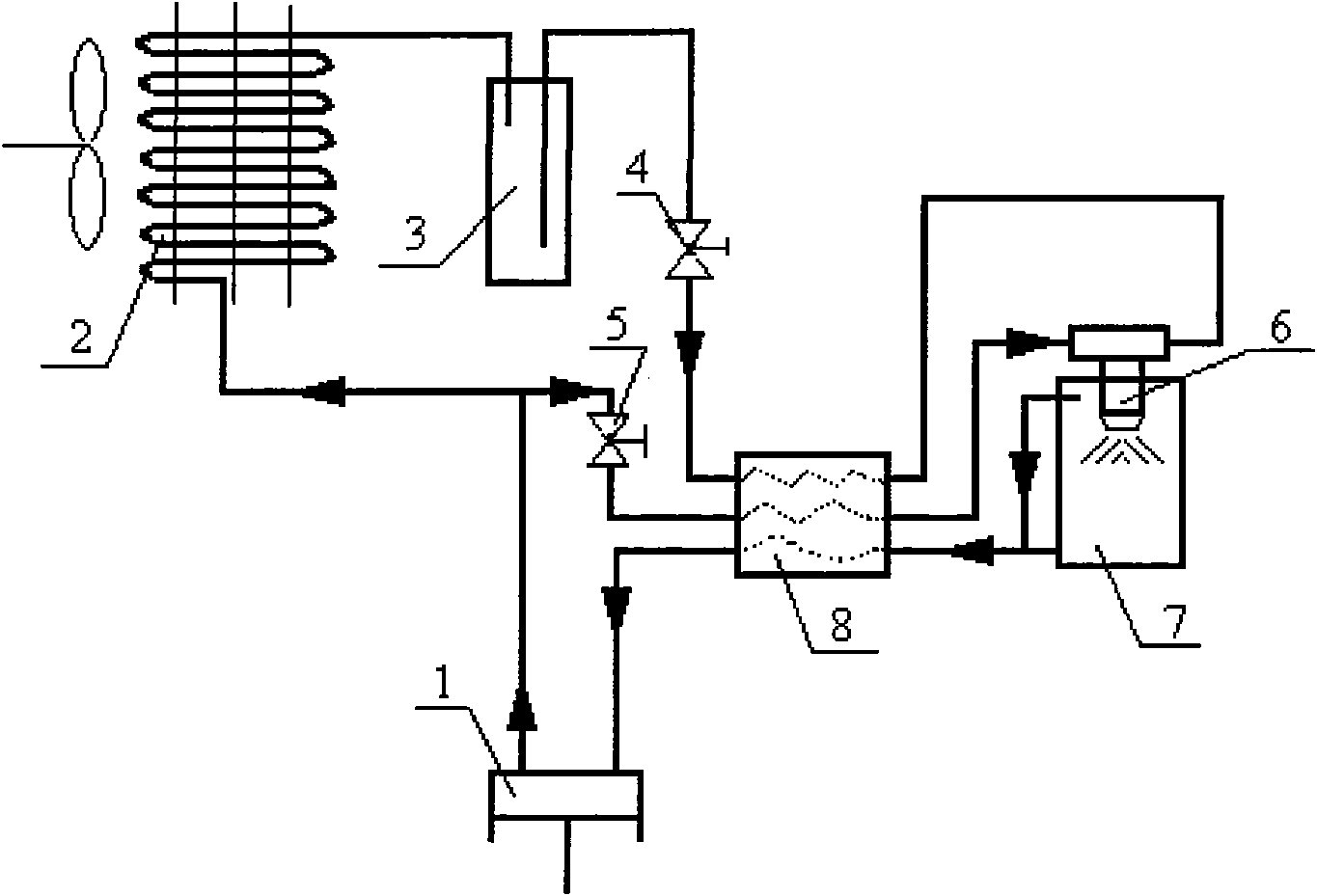
[0031] In order to further ensure the suction dryness of compressor 1 and further reduce the temperature of the liquid source, image 3 The structure of another embodiment of the present invention is as follows: on the basis of embodiment 1, the following structure is added: that is, the output end of the liquid reservoir 3 communicates with the heat through the first control valve 4 The liquid phase inlet of the heat exchanger 8 is connected, and the liquid phase outlet of the heat exchanger 8 is connected with the liquid chamber of the two-fluid nozzle 6 .

[0032] Its workflow is as follows:

[0033] Part of the high-pressure gas is introduced from an opening on the exhaust pipe of the compressor 1 as the gas source, passes through the second control valve 5 and the heat exchanger 8, and then enters the air chamber of the dual-fluid nozzle 6, and the rest of the high-pressure gas flows into the air chamber after being condensed by the condenser 2 The liquid receiver 3, the...

Embodiment 3

[0035] In order to ensure the full utilization of compressor suction dryness and liquid source, Figure 4 Another embodiment of the present invention is given, its structure is: on the basis of Embodiment 1, the following structure is added: that is, the top opening of the heat sink 7 is connected to the heat exchanger 8 through the refrigerant pipeline. The gas phase inlet is connected; the superheated steam outlet of the heat exchanger 8 is connected with the suction pipe of the compressor 1; the bottom opening of the heat sink 7 is connected with the inlet of the liquid pump 10 through the third control valve 9; the outlet of the liquid pump 10 It is connected with the liquid return port of the reservoir 3.

[0036] Its workflow is as follows:

[0037] Part of the high-pressure gas is drawn up from the exhaust pipe of the compressor 1 as a gas source and enters the air chamber of the double-fluid nozzle 6 after passing through the second control valve 5 and the heat exchan...


PUM


Abstract

The invention relates to a dual fluid nozzle atomizing and cooling closed system for a high-power solid laser. In the system, an open pore on the gas exhaust pipe of a compressor is connected with the gas phase inlet of a heat exchanger through a second control valve; the gas phase outlet of the heat exchanger is connected with a dual fluid nozzle chamber; the gas exhaust pipe of the compressor is connected with the input end of a condenser; the output end of the condenser is connected with the input end of a liquid accumulator; the output end of the liquid accumulator is connected with the liquid chamber of the dual fluid nozzle through a first control valve; the nozzle of the dual fluid nozzle stretches into a heat sink; the heat sink is connected with the gas-liquid two-phase inlet of the heat exchanger through a gas exhaust pipeline and a liquid discharge pipeline; and the superheated steam outlet of the heat exchanger is connected with a gas suction pipe of the compressor. The closed cooling system realizes organic combination of a refrigerating system and an atomizing system; gas is input into the gas exhaust pipe of the compressor, so that the defects of introducing a second fluid from outside are overcome; an air pump is saved and the system is simplified; the nozzle replaces a throttle device; and the system can meet the requirement of lower temperature of hot faces.

Description

technical field [0001] The invention relates to a double-fluid nozzle atomization cooling closed system for high-power solid-state lasers, which is especially suitable for the fields of refrigeration and electronic device cooling. Background technique [0002] Diode-pumped solid-state lasers (DPLs) have attracted great interest due to their high efficiency, high beam quality, compact structure, and long lifetime. In recent years, with the successful development of high-power diode lasers, the development of DPL has been promoted and its application in military, industrial, medical, scientific research and other fields. As the power of solid-state lasers increases, the heat load generated by the device becomes larger and the heat dissipation density becomes higher and higher. Therefore, how to eliminate the heat transformed by power dissipation in a timely manner and solve the problem of heat dissipation and cooling is a must for the development of high-power solid-state lase...

Claims


Application Information

Patent Timeline
Patent Type & Authority Applications(China)
IPC IPC(8): H01S3/042
Inventor 田长青司春强邵双全
Owner TECHNICAL INST OF PHYSICS & CHEMISTRY - CHINESE ACAD OF SCI
Why Eureka
Try Eureka