Method for controlling the compressed air supply of an internal combustion engine and a transmission

A technology for compressing air and internal combustion engines, applied to internal combustion piston engines, electrical control, combustion engines, etc., to achieve the effect of improving speed and comfort

Inactive Publication Date: 2011-01-12
ZF FRIEDRICHSHAFEN AG
View PDF7 Cites 13 Cited by
  • Summary
  • Abstract
  • Description
  • Claims
  • Application Information

AI Technical Summary

Problems solved by technology

Thus, such a driver would prefer certain shift points when shifting the transmission

Method used


Image

  • Method for controlling the compressed air supply of an internal combustion engine and a transmission
  • Method for controlling the compressed air supply of an internal combustion engine and a transmission

Examples


Embodiment Construction

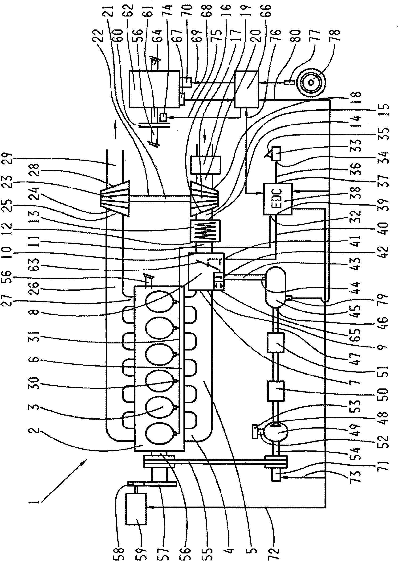
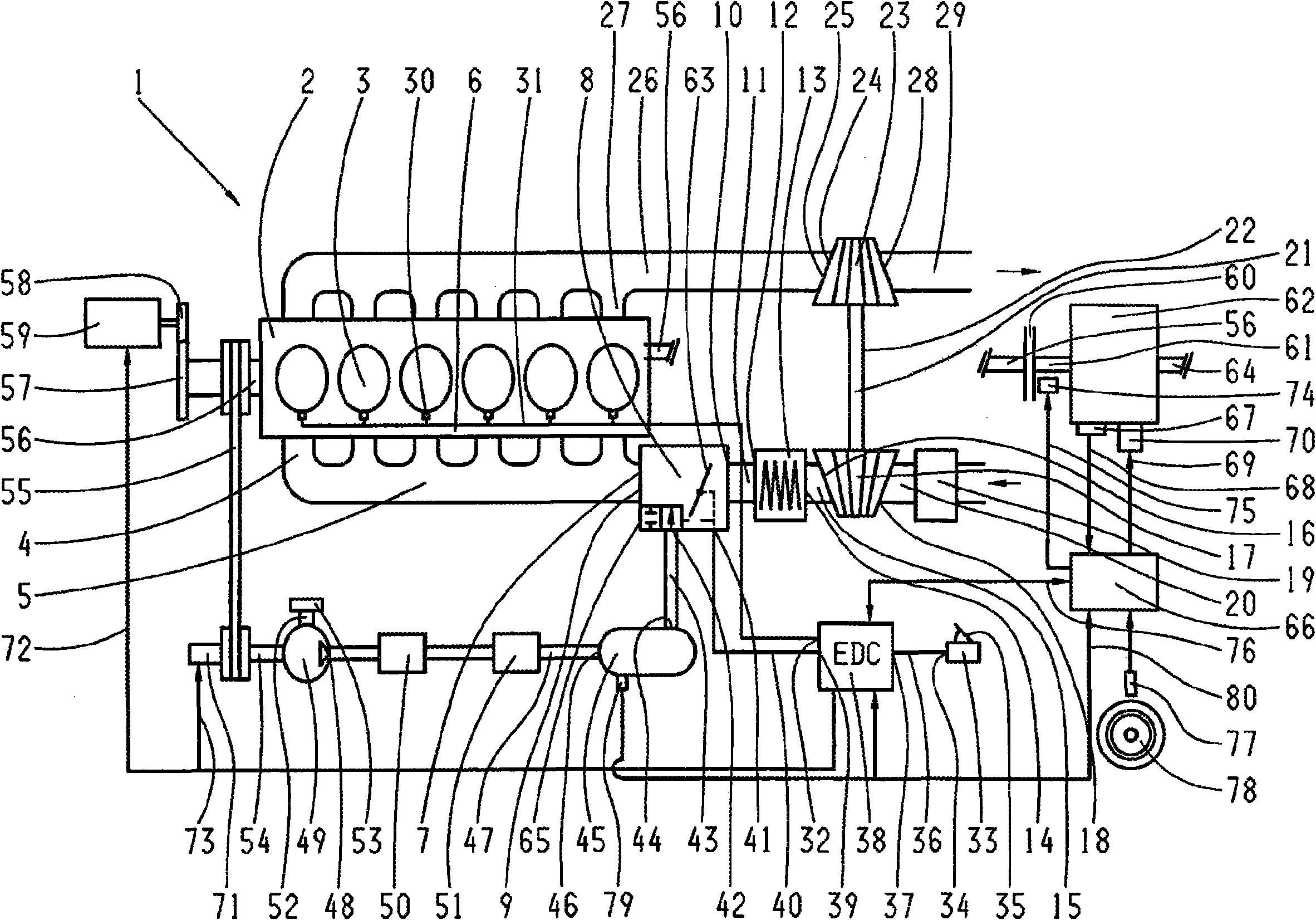
[0032] The invention is explained in more detail below with reference to an exemplary embodiment shown in the single drawing. The main parts of a motor vehicle drive train 1 known per se are shown schematically in this drawing. A diesel engine 2 equipped with a turbocompressor 17 is associated with the drive train 1 and has six cylinders 3 arranged in-line in a cylinder block 6 . The suction line 4 of the cylinder 3 is connected to a main pipe 5 which has a connection flange 7 to which the suction device 8 is connected with its second end connection 9 for the outgoing air. A first end connection 10 for the incoming air is connected via a line 11 to the outflow 12 of charge air coolers 13 whose inflow 14 is connected via a line 15 to the outflow 16 of the turbo compressor 17 . The air filter 19 is connected by a line 20 to the inlet 18 of the turbocompressor 17 . The turbo compressor 17 forms part of a turbocharger 22 whose exhaust gas turbine 23 is connected with its inlet ...


PUM


Abstract

The invention relates to a method for operating an automotive drive train (1) comprising an internal combustion engine (2), a turbocharger (22) associated with said internal combustion engine, a device for injecting additional compressed air into an air intake system (8) of the internal combustion engine (2) and a transmission (62). The aim of the invention is to provide a method which allows thecompressed air injection device to be used in a practical manner in an automotive drive train (1). The method according to the invention is characterized in that the time, duration, pressure and / or volume of the additional compressed air to be injected into the air intake system (8) of the internal combustion engine (2) is controlled depending on the power requested by the driver, the actual speed of the internal combustion engine (2), the load state of the internal combustion engine (2), the vehicle speed and the processes for a transmission (62) ratio change. The invention relates to the interaction of a transmission with a device for supplying a turbo-charged internal combustion engine with compressed air, which interaction is optimal for the operation of said engine.

Description

technical field [0001] The invention relates to a method according to the preamble of claim 1 for operating a drive train of a motor vehicle with an internal combustion engine, a turbocharger assigned to the internal combustion engine, for blowing additional compressed air into the Devices in an air intake system of an internal combustion engine as well as a transmission. Background technique [0002] It is known, for example, from patent application documents WO 2006 / 037564 A1, WO 2006 / 089779 A1 and WO 2006 / 089780 A1 that a piston internal combustion engine equipped with a turbocharger gives a relatively small torque in its low speed range, because the Depending on the system, the amount of air that a conventional turbocharger supplies into the intake system of the engine for increasing the torque is dependent on the exhaust gas flow of the internal combustion engine that drives the turbine of the turbocharger. This phenomenon, known as turbo lag, can be mitigated in its c...

Claims


Application Information

Patent Timeline
Patent Type & Authority Applications(China)
IPC IPC(8): F02D41/00F02D41/02
CPCF02D41/0007F16H61/0213B60W10/06F02B33/44F02B37/04Y02T10/144F02D2200/501F02D41/023F16H59/74F02B37/12F16H63/50F02D2200/602F02D41/0225B60Y2400/435B60W50/06Y02T10/12
Inventor 克里斯托夫·吕沙尔特托马斯·耶格尔罗兰·梅尔
Owner ZF FRIEDRICHSHAFEN AG
Why Eureka
Try Eureka