Air inlet channel of air-breathing type pulse detonation engine

A technology of pulse detonation and air inlet, which is applied in the direction of ramjet engines, combined engines, mechanical equipment, etc., can solve the problems of forward flow resistance and one-way control ability, large windward area, performance loss, etc. problem, to achieve the effect of small forward flow resistance, increase operating frequency, and increase engine thrust

Inactive Publication Date: 2011-01-26
NORTHWESTERN POLYTECHNICAL UNIV
View PDF8 Cites 14 Cited by
  • Summary
  • Abstract
  • Description
  • Claims
  • Application Information

AI Technical Summary

Problems solved by technology

[0004] To sum up, both the existing valved and valveless pulse detonation engines have disadvantages that cannot be ignored: the valve closure of valved pulse detonation engines will bring a large frontal area, resulting in great performance loss; The pneumatic valve of the pulse detonation engine has the problems of forward flow resistance and one-way control ability that cannot be well solved

Method used


Image

  • Air inlet channel of air-breathing type pulse detonation engine
  • Air inlet channel of air-breathing type pulse detonation engine
  • Air inlet channel of air-breathing type pulse detonation engine

Examples


Embodiment Construction

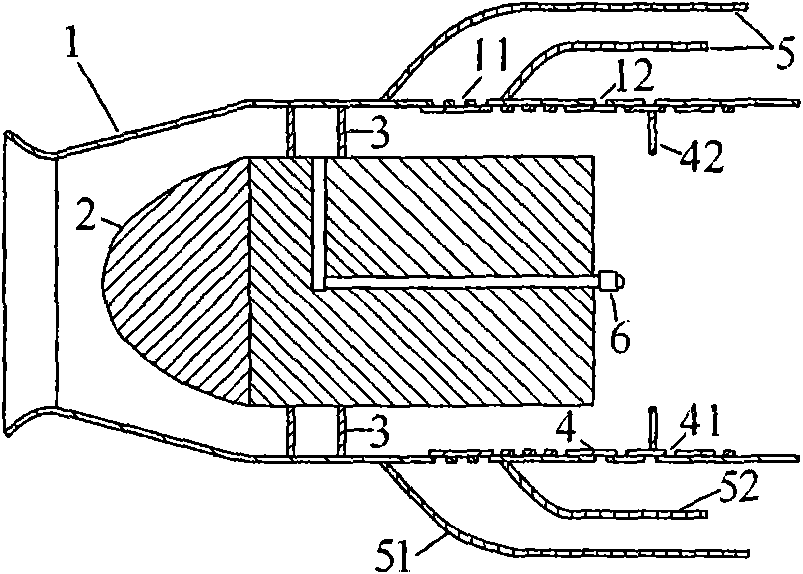
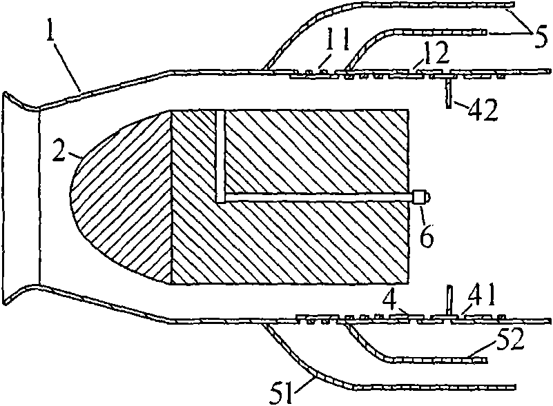
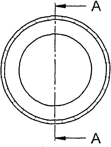
[0035] The air inlet of the pulse detonation engine of the present invention comprises an air inlet shell 1, a central body 2, a bracket 3, an actuating mechanism 4, an air release pipe 5 and a nozzle 6, and the inlet opening is forward, as shown in FIG. 1 . Two or more brackets 3 can be evenly distributed along the circumferential direction, as shown in Figure 1(a). The actuating mechanism 4 is driven by an electric actuator or a hydraulic mechanism, and can be made into an integral axially forward and backward actuating structure, as shown in FIG. 2 , or can be composed of multiple actuating units, as shown in FIG. 3 . The air intake housing is provided with multiple rows of incoming flow vent slots 11 and reverse flow vent slots 12 from the front to the rear at two-fifths to four-fifths, and is used in conjunction with the vent slots 41 on the actuator 4. . The incoming air discharge hole groove 11 and the reverse flow air release hole groove 12 are respectively distribute...


PUM


Abstract

The invention discloses an air inlet channel of an air-breathing type pulse detonation engine. In the channel, an air inlet channel shell and a central body form an air inlet ring cavity; fuel oil is axially jetted from a nozzle of a rear end face of the central body to the air inlet channel; an air release hole groove is formed in an inlet of an air release tube facing the lower part of the air inlet channel on the air inlet channel shell; an actuating mechanism actuates back and forth along an axial direction in the air inlet channel; a plurality of rows of hole grooves are formed on the actuating mechanism; an actuating block is arranged on the actuating mechanism; and the hole grooves can be separately or simultaneously coincided with the air release hole grooves of the air inlet channel shell by axial actuation. The air inlet channel has the advantages of achieving smaller forward flow resistance under the condition of high-speed flight, simultaneously inhibiting and making use of a counter flow, improving the thrust force of the engine, increasing the air release speed, and improving the working frequency of the engine.

Description

technical field [0001] The invention relates to the technical field of engines, in particular to an engine intake duct. Background technique [0002] The pulse detonation engine is a new concept engine that uses intermittent or pulse detonation waves to generate thrust. Unlike the deflagration combustion in conventional engines (such as turbojet engines and piston engines, etc.), the combustion process in pulse detonation engines is detonation combustion. The difference between detonation and deflagration is that it has a high supercharging capacity. The pressure ratio before and after the detonation wave can reach 20-40 times in the mixture of air as the oxidant, and the strong shock wave generated will be reversed back to the intake air. Therefore, the detonation combustion chamber has high requirements on the intake port. [0003] To prevent detonation-induced flow oscillations from causing intake port failure, pulse detonation engines typically require an intake / detona...

Claims


Application Information

Patent Timeline
Patent Type & Authority Applications(China)
IPC IPC(8): F02K7/20
Inventor 王治武严传俊范玮郑龙席
Owner NORTHWESTERN POLYTECHNICAL UNIV
Why Eureka
Try Eureka