Three-dimensional fluorescence nano microscope imaging method and system, and image equipment

A three-dimensional fluorescence and microscopic imaging technology, applied in fluorescence/phosphorescence, material excitation analysis, etc., can solve the problems of difficult sample observation and low molecular positioning accuracy, improve lateral and axial positioning accuracy, and achieve axial selectivity Easy to stimulate and observe the effect

Active Publication Date: 2011-02-02
SHENZHEN UNIV
View PDF5 Cites 32 Cited by
  • Summary
  • Abstract
  • Description
  • Claims
  • Application Information

AI Technical Summary

Problems solved by technology

[0004] The purpose of the embodiments of the present invention is to provide a three-dimensional fluorescence nano-microscopic imag

Method used


Image

  • Three-dimensional fluorescence nano microscope imaging method and system, and image equipment
  • Three-dimensional fluorescence nano microscope imaging method and system, and image equipment
  • Three-dimensional fluorescence nano microscope imaging method and system, and image equipment

Examples


Embodiment 1

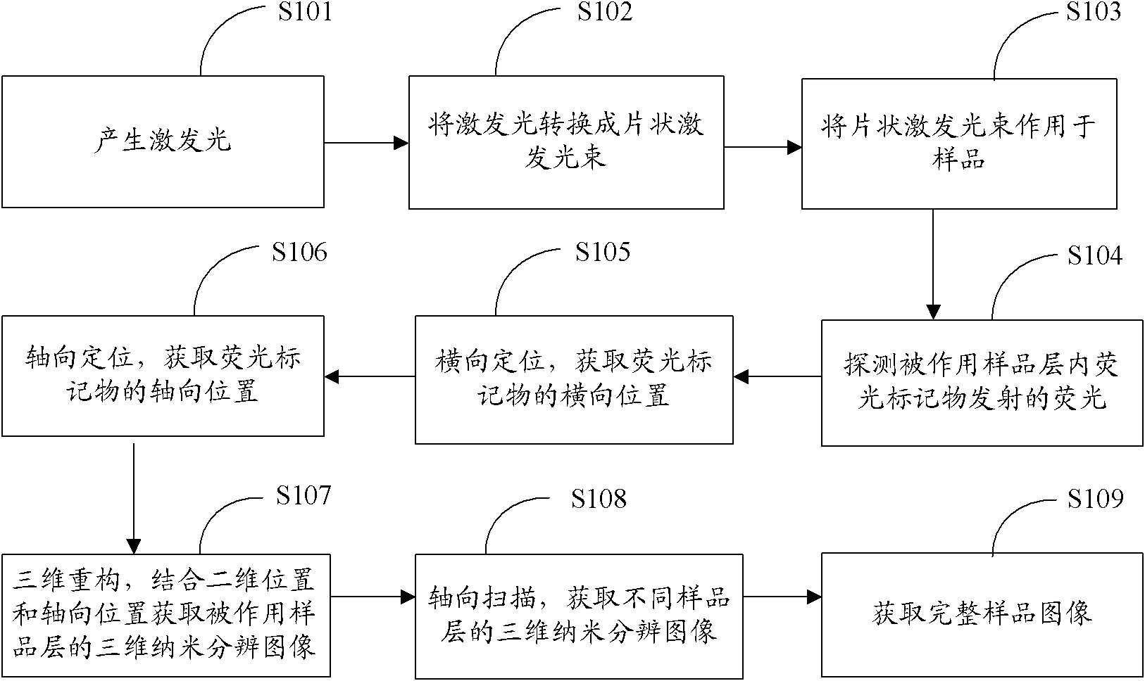
[0051] figure 1 The implementation process of the three-dimensional fluorescence nanomicroscopic imaging method provided by the first embodiment of the present invention is shown, and the details are as follows:

[0052] In step S101, generating excitation light;

[0053] In step S102, converting the excitation light into a sheet-shaped excitation beam;

[0054] In step S103, applying a sheet-shaped excitation beam to the sample;

[0055] In step S104, detecting the fluorescence emitted by the fluorescent marker in the sample layer;

[0056] In step S105, horizontal positioning is used to obtain the two-dimensional position of the fluorescent marker;

[0057] In step S106, axial positioning, obtaining the axial position of the fluorescent marker;

[0058] In step S107, three-dimensional reconstruction, combining the two-dimensional position and axial position to obtain a three-dimensional nano-resolution image of the applied sample layer;

[0059] In step S108, scan axial...

Embodiment 2

[0062] In the embodiment of the present invention, the excitation light should be able to achieve sparse excitation of the fluorescent marker, and its wavelength should be selected from the excitation spectrum of the fluorescent marker with stronger excitation. The light source of the excitation light can choose a laser light source with better monochromaticity.

Embodiment 3

[0064] In the embodiment of the present invention, the sheet-shaped excitation light beam can be obtained by the following method: After the excitation light generated by the light source is collimated and expanded, the sheet-shaped beam is formed by the sheet-shaped beam acquisition element; The depth of focus of the sheet-like beam, the thickness of the sheet-like beam with a large depth of focus passing through the illumination objective lens is greatly reduced, so that the beam is approximately an ultra-thin sheet-like parallel beam within the focal depth range.

[0065] As an embodiment of the present invention, the order of magnitude of the depth of focus of the sheet-like excitation beam is higher than the order of magnitude of the radial length of the applied sample layer in the direction of the excitation light path, and the thickness of the sheet-like excitation beam is less than 1 micron.


PUM

PropertyMeasurementUnit
Thicknessaaaaaaaaaa

Abstract

The invention is suitable for the field of microscope imaging, and provides a three-dimensional fluorescence nano microscope imaging method and a three-dimensional fluorescence nano microscope imaging system, and image equipment. The method comprises the following steps of: producing exciting light; converting the exciting light into a laminar exciting beam; making the laminar exciting beam act on a sample; detecting a fluorescent light emitted by a fluorescent label in the sample layer on which the laminar exciting beam acts; transversely positioning to acquire the two-dimensional position of the fluorescent label; axially positioning to acquire the axial position of the fluorescent label; three-dimensionally reconstructing, combining the two-dimensional position with the axial position to acquire a three-dimensional nano resolution image of the sample layer on which the laminar exciting beam acts; axially scanning to acquire the three-dimensional nano resolution images of different sample layers; and acquiring the three-dimensional nano resolution image of the complete sample. Through the three-dimensional fluorescence nano microscope imaging method and the three-dimensional fluorescence nano microscope imaging system, and the image equipment, the high-precision three-dimensional nano microscope imaging is realized by taking the laminar light beam as the exciting light, and combining with axial scanning, and the method, system and equipment are suitable for three-dimensional microscope imaging of the thick sample, such as cells in the biological field and the like, and solve the problems that the positioning accuracy of molecules in the thick sample is low and the sample is difficult to observe.

Description

technical field [0001] The invention belongs to the field of microscopic imaging, and in particular relates to a three-dimensional fluorescent nanometer microscopic imaging method, system and imaging equipment. Background technique [0002] Nano-resolution fluorescence imaging can visually display the spatial distribution of labeled molecules in the labeled object with nanoscale spatial resolution, and can be used to study the interaction process between labeled molecules, and can be used in the biological field to study DNA in cells , The interaction and movement rules between RNA and protein molecules. At present, the commonly used imaging method is to use the switching effect of the fluorescent marker itself to perform positioning micro-imaging technology, and to perform nano-resolution imaging through time-division multiplexing, centroid positioning and image compounding, for example, photosensitive localization microscopy (PALM), random Optical reconstruction microscop...

Claims


Application Information

Patent Timeline
IPC IPC(8): G01N21/64
Inventor 于斌陈丹妮屈军乐牛憨笨
Owner SHENZHEN UNIV
Why Eureka
Try Eureka