Physiotherapy device power amplifier
A technology of a power amplifier and a physiotherapy instrument, which is applied in the field of power amplifiers of short-wave therapy machines, can solve the problems of burnout of the final stage power amplifier, short service life, low frequency accuracy, etc., and achieves low working voltage, long service life and high accuracy. high effect
- Summary
- Abstract
- Description
- Claims
- Application Information
AI Technical Summary
Problems solved by technology
Method used
Image

Examples
Embodiment 1
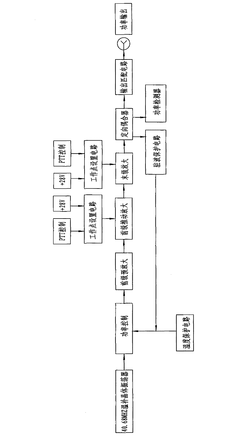
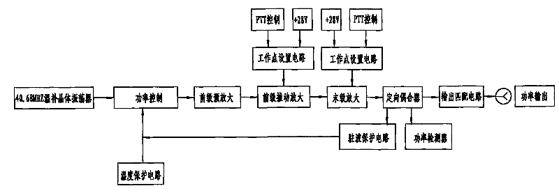
[0016] Such as figure 1 As shown, the present invention includes a 40.68MHz temperature-compensated crystal oscillator and a front-stage pre-amplification circuit connected to the temperature-compensated crystal oscillator. stage amplifying circuit, and the output end of the final stage amplifying circuit is connected to the output matching circuit. Both the above-mentioned pre-stage driving amplifier circuit and the final stage amplifier circuit are provided with respective operating point setting circuits. Usually, the operating point setting circuit includes a PTT control circuit and a power supply circuit, wherein the power supply circuit generally adopts a voltage of 28V.
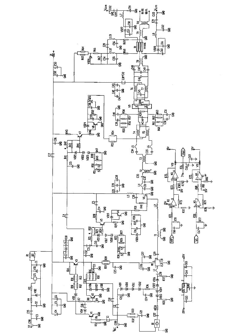
[0017] In order to realize the transistorization of the power amplifier of the physical therapy instrument, a pre-stage push amplifier is set in the pre-stage push amplifier circuit, and a final power amplifier is set in the final stage amplifier circuit. Both the pre-stage push amplifier and the fina...
Embodiment 2
[0025] The difference between this embodiment and Embodiment 1 is that in this embodiment, in order to ensure the normal operation of the pre-stage push amplifier V6 and the final power amplifier V9, the output end of the above-mentioned final power amplifier circuit is connected to a directional coupler, and the directional coupling The output end of the coupler is connected to the output matching circuit; among them, the directional coupler is connected with a standing wave protection circuit and a power detector, such as figure 1 shown.
[0026] Specifically, the transformer T8 sends the amplified signal to the directional coupler D1, and then the final output impedance matching is performed by the output transformers T9 and T10, and finally the signal is output from the output terminal of the output transformer T10, and sent to the back-end tuning indicating circuit. Among them, diodes VD26, VD27, VD28 and peripheral resistors, capacitors and inductors constitute the powe...
Embodiment 3
[0030] The difference between this embodiment and Embodiment 1 is that in this embodiment, in addition to the PTT control circuit, an anti-EMI electromagnetic compatibility circuit is also included in the operating point setting circuit of the pre-stage drive amplifier circuit and the final stage amplifier circuit. . Specifically, in this implementation, the 28V voltage supplied by the power supply is sent to the power amplifier through the feed-through filter, so it also includes an anti-EMI electromagnetic compatibility circuit. Due to the addition of new anti-EMI materials, this can be effectively improved. Electromagnetic Compatibility of Power Amplifiers.
[0031]In addition, in this embodiment, the turn ratio of the input and output coils of the output transformer T10 in the output matching circuit is 1:8, and its output impedance is 400Ω.
[0032] Other technical characteristics are identical with embodiment 1.
PUM
 Abstract
Description
Claims
Application Information
 - R&D
- Intellectual Property
- Life Sciences
- Materials
- Tech Scout
- Unparalleled Data Quality
- Higher Quality Content
- 60% Fewer Hallucinations
Browse by: Latest US Patents, China's latest patents, Technical Efficacy Thesaurus, Application Domain, Technology Topic, Popular Technical Reports.
© 2025 PatSnap. All rights reserved.Legal|Privacy policy|Modern Slavery Act Transparency Statement|Sitemap|About US| Contact US: help@patsnap.com