Self-driving magnetorheological damper

A damper and magnetorheological technology, applied in the field of engineering vibration reduction, can solve problems such as inability to guarantee, obstacles to the development and application of vibration control technology, and impact on damper performance and quality, and achieve good stability.

Inactive Publication Date: 2011-02-09
CHINA ELECTRIC POWER RES INST +1
View PDF6 Cites 13 Cited by
  • Summary
  • Abstract
  • Description
  • Claims
  • Application Information

AI Technical Summary

Problems solved by technology

[0003] However, the yield fluid damping devices currently on the market still belong to the category of intelligent-semi-active control technology. On the one hand, the damper drive needs to be controlled by an external power supply, which has high requirements for the stability of the power supply. On the other hand, the effective performance of the damper largely depends on the decision-making and driving of the external control center, so there are high r

Method used


Image

  • Self-driving magnetorheological damper
  • Self-driving magnetorheological damper

Examples


Embodiment 1

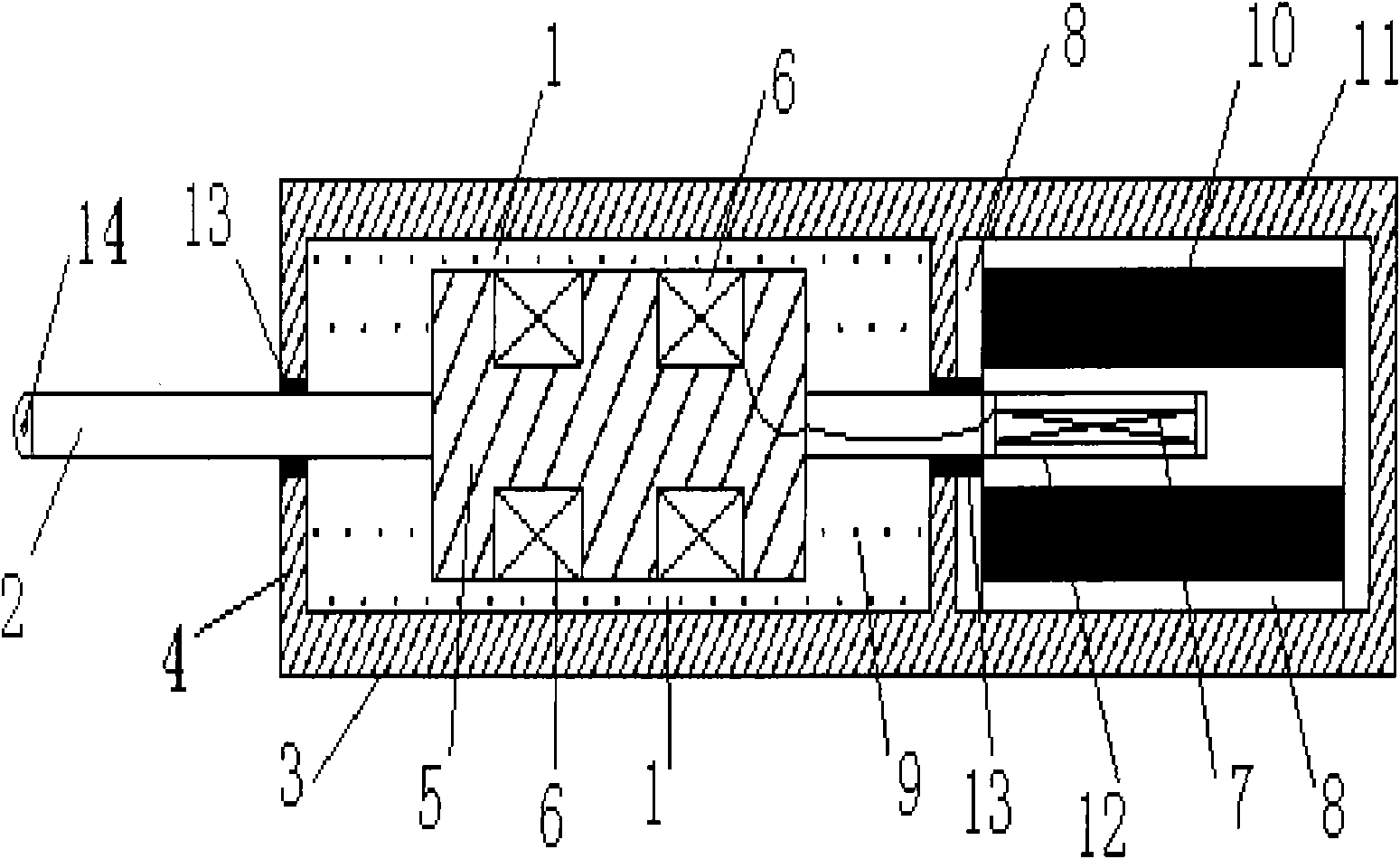
[0033] The self-driving magnetorheological vibration damping damper of this embodiment, such as figure 1 As shown, the damper is provided with a self-induction device 11; including a cylinder 3, a piston 5, and an electromagnetic coil 6. The electromagnetic coil 6 is wound on the outer surface of the piston 5, and the inner wall of the cylinder 3 and the outer wall of the piston 5 are provided Throttle channel 1, the cylinder tube 3 is equipped with magnetorheological fluid, and the throttle channel 1 is equipped with a yielding liquid 9; the self-induction device 11 is equipped with a magnetic shield 8, a powerful magnet 10 and a power rod 12. The rod 12 is provided with an induction coil 7; the power rod 12 is consolidated with one end of the piston rod 2 passing through the piston 5, and reciprocates together with the piston rod 2.

[0034] The power seal 13 and the end cover 4; the connection between the piston rod 2 and the cylinder 3 and the connection between the power rod ...

Embodiment 2

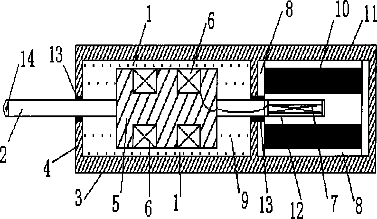
[0037] The self-driving magnetorheological vibration damping damper of this embodiment, such as figure 1 As shown, the damper is provided with a self-induction device 11; including a cylinder 3, a piston 5, and an electromagnetic coil 6. The electromagnetic coil 6 is wound on the outer surface of the piston 5, and the inner wall of the cylinder 3 and the outer wall of the piston 5 are provided Throttle channel 1, the cylinder tube 3 is equipped with magnetorheological fluid, and the throttle channel 1 is equipped with a yielding liquid 9; the self-induction device 11 is equipped with a magnetic shield 8, a powerful magnet 10 and a power rod 12. The rod 12 is provided with an induction coil 7; the power rod 12 is consolidated with one end of the piston rod 2 passing through the piston 5, and reciprocates together with the piston rod 2.

[0038] The power seal 13 and the end cover 4; the connection between the piston rod 2 and the cylinder 3 and the connection between the power rod ...


PUM


Abstract

The invention relates to a self-driving magnetorheological damper, which is provided with a self-induction device and comprises a cylinder barrel, a piston and an electromagnetic coil, wherein the electromagnetic coil is winded on the outer surface of the piston, a throttling channel is arranged between the inside wall and the outside wall of the cylinder barrel, magnetorheological fluid is filled in the cylinder barrel and yield fluid is filled in the throttling channel; a magnetic shielding body, a powerful magnet and a power rod are arranged in the self-induction device, and an induction coil is arranged in the power rod; and the power rod is fixedly connected with one end of a piston rod penetrating through the piston and moves in a reciprocating way along the piston rod. The damper has the characteristics of active tuning and environment self-adaptation, avoids using external energy and sensor system, is characterized by automatically changing damping property along the environment and has high stability and robust performance.

Description

Technical field [0001] The present invention relates to engineering vibration reduction technology, in particular, to a phase vibration damping damper. Background technique [0002] Fluid damping technology is an excellent vibration reduction control method. It is based on the principle of pore flow. It adjusts the value range of the damping coefficient by adjusting the size of the variable cross-section pores. It has a good vibration reduction and energy consumption effect. The emergence of smart materials represented by magnetorheological fluids has injected new life into the development of damping technology. They combine fluid damping technology with active control strategies, and have gradually played a great role in various fields of vibration reduction. value. [0003] However, the yielding fluid damping devices currently on the market still belong to the category of smart-semi-active control technology. On the one hand, the damper drive needs to be controlled by an externa...

Claims


Application Information

Patent Timeline
IPC IPC(8): F16F9/53
Inventor 夏开全刘建军
Owner CHINA ELECTRIC POWER RES INST
Why Eureka
Try Eureka